And so it goes.
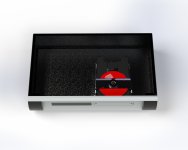
OK so 3D CAD is fun and the process is informative. I now understand why folks get teary eyed over mech quality, or lack thereof. However, it's also a really good for putting things in a box before any proper destruction has begun.
But some actual, useful, fiddling has intruded and I decided to look properly at the FCD's valve output stage. It's not an X10-D well not exactly... (yes I'm well aware that the x10-d is electrically unremarkable, but its a reference - don't shoot me)
No voltage doubler, on this board at least, and a different (than the X-10D) approach to the B+ Supplies and grounding of the first valve section. Also it does have a relay grounding the output during start up but imagine that in the schematic if you need to
The PSU board needs more disassembly than I want to commit to, before I have a plan that reaches past tomorrow. I'll get there no doubt.
Next step is to measure some voltages I suppose?
Andy
OK so 3D CAD is fun and the process is informative. I now understand why folks get teary eyed over mech quality, or lack thereof. However, it's also a really good for putting things in a box before any proper destruction has begun.
But some actual, useful, fiddling has intruded
and I decided to look properly at the FCD's valve output stage. It's not an X10-D well not exactly... (yes I'm well aware that the x10-d is electrically unremarkable, but its a reference - don't shoot me)No voltage doubler, on this board at least, and a different (than the X-10D) approach to the B+ Supplies and grounding of the first valve section. Also it does have a relay grounding the output during start up but imagine that in the schematic if you need to
The PSU board needs more disassembly than I want to commit to, before I have a plan that reaches past tomorrow. I'll get there no doubt.
Next step is to measure some voltages I suppose?
Andy
Attachments
So last one for a bank holiday
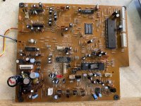
Lets 'take a dive' into the FCD main board, which I just realised (slowpoke) was easier to get to than I thought by just cutting the optical SPDIF wires. Not using them again anyway
Then a genuine LOL which I thought I'd share
See photo, yeah in todays money a £3K unit.... So Normally I have the greatest of respect for past engineers and the limitations of their time, but scrubbing out chip numbers 'so no one can tell' is the equivalent of kindergarten!
Funny - because its SO bad - automatic 'Hall of shame' for you! No matter whom you may be (and perhaps whatever you created next)
I will admit to a soft spot for M.F. as this thread attests, but 'FFS' did they employ five year olds? Was that allowed in the 90's?
Still chuckling
Attachments

Turns out it's just +/- 25v for the tubesNext step is to measure some voltages I suppose?
Andy
and 12v for the heaters in series (regulated with 7812)Very nice. I would place the electrolytic capacitors more apart from the tube due to heat.
I see your point, but it's sort of OK, max bulb temp is 170c and a 15mm gap. In real life the caps are even smaller. Not that MF ever lavished money on expensive electrolytics though; so these are rated at 85c
Andy
I still don't understand, but given the heart you put into it, I will continue to follow your work.
Yep I know this is a silly project but I'm not letting logic intrude too much
and thank youAll I have done thus far is establish a 'childhood' crush is rather disappointing. "all fur coat and no knickers" if I'm allowed that.
- CD board - TEAC CD3500 < OK that's unfair it's not bad, just not, 'what I want'
- Power supply - two transistor regulated for a +/-25v supply - way to low. Input the resulting circuit in TubeCAD and it politely tells you that there "must be some current to operate"
- Buffer circuit, v1 of the X10d / standard buffer. So primordial 'meh'
The plan then: ("plan" ha ha)
- Output: new buffer stage which for sentimental reasons will be based on a two tube layout and probably a 6DJ8. I contemplated doing something with the 5703 or 6112 or even a VFet (2SK79) but a 6DJ8 is hard to top.... At the moment and it fits the tube narrative
- PSU - I'll need new transformer here (so that's gone too). Just going to be really simple and generate proper voltages, likely Maida regulation because it works and the LM317
- CD player part (yep that's why we're here) VRDS9 might be a good donor if I can find one reasonably, but this is going to be on a whim. I like HDCD so that'd be nice to throw into the mix too
Andy
There, I understand"all fur coat and no knickers"
Copland worked around this base by mixing generations and pieces, I really liked the result, especially the CDA-288 which is one of my favorite CD players.CD player part (yep that's why we're here) VRDS9 might be a good donor if I can find one reasonably
Don't neglect the work on the chassis, it's really important, giving mass and inertia to the whole thing really gives very good results.
A few years ago in my CD723 period, I had poured a block of concrete, fixed the entire mechanics of the player on it then suspended the whole thing in three points with very very fine fishing wire, that alone had made a very big difference .
The funniest thing is the path, the quest, not the destination.
Copland. I see that and agree
In fact this would be a somewhat shorter journey if the VRDS10 'slab' would fit in any normal sized box - it does not!
As far as chassis goes, the 3D CAD that I'm boring you with - opens the door to some very nice (?) mods that will stiffen up the base plate and arch of the KSL210 and so on... I'm some way off that, but it's on the list too
Andy
In fact this would be a somewhat shorter journey if the VRDS10 'slab' would fit in any normal sized box - it does not!
As far as chassis goes, the 3D CAD that I'm boring you with - opens the door to some very nice (?) mods that will stiffen up the base plate and arch of the KSL210 and so on...
I'm some way off that, but it's on the list tooAndy
- Home
- Source & Line
- Digital Source
- Musical Fidelity FCD. A journey