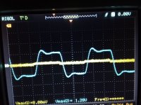
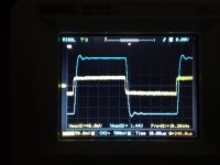
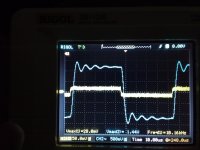
It looks like you have a tame HF stability and spectrum level response. Open loop response has no consequences, given your closed loop responses are ok.
You could extend your LF testing down to 1Hz, as your signal generator can manage that. You may have to use X-Y scope plot, with persistence, to get a good view of what is happening. One aim would be to step down from 10Hz in say 1Hz increments, and check if there is any significant peaking occurring down where the output transformer is rolling off. Perhaps start at low enough signal level that any peaking doesn't cause high power levels - and then step up signal a bit to see how any peaking is affected. You may find no significant changes worth reporting until well below 5Hz.
You could extend your LF testing down to 1Hz, as your signal generator can manage that. You may have to use X-Y scope plot, with persistence, to get a good view of what is happening. One aim would be to step down from 10Hz in say 1Hz increments, and check if there is any significant peaking occurring down where the output transformer is rolling off. Perhaps start at low enough signal level that any peaking doesn't cause high power levels - and then step up signal a bit to see how any peaking is affected. You may find no significant changes worth reporting until well below 5Hz.
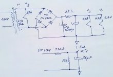
One more question please...This is my 6.3V heaters supply scheme. V1,V2 are DC suplied, V3 AC suplied. The Heaters are referenced to ground by dc return rail only. Works nice and quiet. Now, I want to elevate heaters more to say 30Vdc. from a B+ voltage divider. I wonder how is the best to reference the heater supply to the 25V elevation point please ? Should I just stack it on the top or from a virtual center tap built on ac or dc side please? Thanks.

Last edited:
Hey. V3 is 6n6p driver stage and V2 is first stage in earlier schematic V1 is a integrated preamp stage I didn't figured. The DC supply was necessary to heat v1,v2 - 6n9s tubes. Really noisy tubes works only dc in my circuit. With AC supply - DC elevation helps with negative voltage only, positive voltage elevation did not help at all. Still, elevating by negative voltage the noise not completely gone, more the cathode resistors are not decoupled at all- who make h-k coupling more sensitive. So, DC supply rules. But with V2 6n9s into first stage /cathodyne position the inverter cathode is up 100v, and will raise it up to 125v perhaps, as consequence to get a little bit more headroom of first stage (1.5V around). A slight elevation (30V) to put Vh-k potential into the safe range I considered please. Thanks.
Last edited:
One more question please:
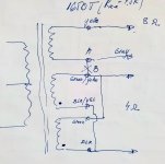
Do I have any benefit using a different secondary winding for nfb ? and not necessary the winding I used for speaker please ?
I used a Hammond 1650T. The output wiring is presented in my sketch. Decided to use the 4 ohm output only now I have a winding available. The points 'A' and 'B' was initial internaly connected but I did it apart. So, now I may use yellow / gray wires as separate winding for nfb (with the gray tied to the common). Do I get any advantage using it instead to use the 4 ohm speaker output please ? Thank you.

There is a slight difference to drive it for 4 ohm and 8 ohm impedance to onset clipping with 20db nfb applied. In 8 ohm it ask for 800 mVpk input, with 4 ohm 900mVpk for 32Vpk output. That was close for 1V initial cathode bias. It was necessary to lift it to 1.5V to get a bit of convenient headroom but this raised the grid voltage to next stage to 125V around. The 6sl7 cathodyne is still well usable biased at 2.4V around with 410V but h-k potential is way above the limit so I elevated the heaters a bit. See #105. Thanks.
Last edited:
Hey again. Quick question please: May an undampened low freq oscillation of an LC filter in power stage to create premises of low freq instability when nfb apply please ? I just thinking...my power plates are supplied from first node decoupled with 500uF cap. Next I used a 4H choke to next 500uF decoupled supply node to the screens. Still the 30 ohm residual resistance of the coil is not enough to dampen the LC network oscillation at 3.5Hz. I may use a hundred ohm series resistor to be sure I don't get any lf overshot but : Do it have any influence to improve low freq stability margin please ? (Remember my tubes are pentode connected).Thanks.
Last edited:
- Home
- Amplifiers
- Tubes / Valves
- Williamson first stage question
