I instantly jumped to open the window .....Ironically, I've just achieved the kind of "magic smoke" success that xrk971, redjr and bloqhed described. I stupidly decided to save some money by purchasing a few TDA7293 ICs from a Chinese vendor and -- shockingly -- things did not go well. Lesson learned and the order I had planned on placing with Newark now includes a few TDA7293s. I'll continue buying standoffs, screws, knobs, feet and other basic parts from inexpensive Chinese sources but will spend the few extra bucks to get the operative components from reliable sources.
And yup, the attached clip is exactly what you'd expect.
Regards.
SRMcGee, you should have been warned sufficiently to avoid buying cheap Chinese stuff. Anyway, an impressive video!
Kay:
You are absolutely right: the warnings against cheap Chinese components are everywhere. I certainly knew better but thought "maybe it's worth the chance."
It wasn't.
Regards.
Folks:
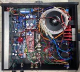
This project took a while longer than expected but is now finished. As background, my younger daughter and I built a Gainclone together about 14 years ago (see https://www.diyaudio.com/community/threads/chip-amp-photo-gallery.79303/page-63#post-1988901). That amp is on its last legs now (i.e., another project for me!) and Jamie suggested we work on a new project together. I needed no convincing. My daughter is now a very busy journalist with limited availability. When time permitted, she came home to visit and we'd find a few hours to work on her amp. She did most of the soldering and drilling; I did the rest. We had a few problems along the way (e.g., see post #1,017) but persevered and are very happy with the result. This new integrated amplifier will soon be installed in Jamie's apartment where it will be thoroughly enjoyed.
This was great fun. Projects like this don't happen without the amazing generosity and support of the members of this fine community. In this case, many, many thanks to Jhofland, Dibya, Prasi and the endlessly enterprising xrk971! I appreciate your fine work and the opportunity to spend more time with one of my kids.
Regards,
Scott
Attachments


Hi.
Thank you for the information.
I was curious if someone had tried this, but I also read that it could be troublesome with some <8ohm speakers.
Anyway I'm looking for a new project with balanced poweramps, but i guess I need something else than a chipamp for it to succeed.
Thank you for the information.
I was curious if someone had tried this, but I also read that it could be troublesome with some <8ohm speakers.
Anyway I'm looking for a new project with balanced poweramps, but i guess I need something else than a chipamp for it to succeed.
Almost any amp can be made to be balanced output. You need to get twice as many amps but power can be as much as 4x. One amp for each leg - just make sure output -ve doesn’t touch GND. One amp is connected to +ve of the balanced and other to -ve end. The preamp needs to be balanced of course to control volume.
Yes, most possibly xrk had this arrangement in mind. Anway, only a minuscule part of commercially available preamps or DIY designs feature balanced outputs. Hence, a phase splitter is required. Or we drive the inverting amp by it's inverting input, being it a resistor of the same value as the feedback resistor from the other amp's output.
Best regards!
Best regards!
@Kay Pirinha
I have the balanced source as a DAC (true differential)... I'm probably also going to make an OPA1632 preamp! This was my initial plan that is.
So with this in mind do you also believe it would work.
Thanks anyway.
I have the balanced source as a DAC (true differential)... I'm probably also going to make an OPA1632 preamp! This was my initial plan that is.
So with this in mind do you also believe it would work.
Thanks anyway.
I am late to this thread, but I have followed with interest what seems to be quite a bit of struggling with the DC servo circuit. I'm using the schematic in the first post for reference.
I find the configuration of the Xmas servo amp very unusual/suspect and suggest modifying it to be a more conventional non-inverting integrator stage. The first peculiar symptom was the need to reduce the value of R15; if the U6 servo opamp is able to deliver +/- 12V, the R3/R15 voltage divider should be able to accommodate about +/- 41mV input offset error, but the TDA7293 data sheet indicates maximum offset error is only 10mV. The servo should have plenty of "control authority."
See the attachment for an example of a non-inverting integrator as the servo amp. The modified Xmas servo will resemble this cricuit.
I suggest the following as a path to modifying the servo.
1. Remove R15. With input shorted, measure the TDA7293 PA output DCV. If C2//C17 are present, the output voltage is interesting as it is what the circuit delivers without using servo nulling. Then if C2//C17 are present, short them so the the PA has flat gain to 0Hz and note voltage. Assuming gain is the specified 27.7, DCV at output should be less than about +/- 277mV. Once implemented, the servo should drive this initial voltage to only a few mV.
2. Modify the passives near U6 as follows:
a. Remove R16 and R17.
b. Remove C127 and install at the C28 site so that C28 is 1uF. C27 remains 1uF.
c. Install R15 = 215k.
The PA output voltage should null to near 0V, essentially to about the offset error inherent in U6.
Settling will be very slow. The servo generates a high-pass function; the corner frequency (-3dB re nominal of 29.8dB) is
Fo = R1/(2*Pi*R15*R19*C27). With the specified values, the -3dB corner is about 0.05Hz. After confirming proper operation, I would probably revise C27=C127= 0.1uF film and R18=R19= 33.2K. (i.e. about 5Hz.)
Attachments
- Home
- Amplifiers
- Chip Amps
- Xmas Amp - Dibya's TDA7293 by Jhofland