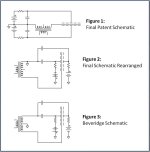
The Beveridge drive system is equivalent to that used by Final, only the ground reference location is changed. Both use low resistance diaphragms and have driving forces that are inherently non-linear.What are your thoughts about the Beveridge inverted drive method...
The advantage of the Beveridge circuit is mainly in its use for direct drive systems where the same output can be achieved with amplifiers having half the HV requirement.
See also: Beveridge-vs-Final-ESL-Configuration

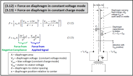
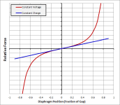
Looking at the Force equations for the Constant Voltage Mode compared to Constant Charge(taken from the Baxandall paper golfnut mentioned), you can see the source of the odd harmonic distortion in the squared terms, and the even harmonic from diaphragm offset. If you just look at the Force generated when the diaphragm is positioned at different points in the gap, you can see that distortion will be reasonably low if excursion is less than 10% of the gap. As excursion passes 20% the distortion increases exponentially.


If numerical methods are used to solve equations of motion with the constant voltage driving force, you can see how distortion products are affected by different parameters.
- With theoretical perfect symmetry resulting in no diaphragm offset, only odd order harmonics are generated
- When diaphragm is offset from center as in all practical ESLs, even harmonics will also be generated.
- The ratio between even and odd harmonics depend on
- magnitude of the diaphragm offset
- magnitude of the diaphragm excursion
- ratio of Vbias to Vsignal
1) No offset with excursion of 30% of gap
2) With 5% gap offset and 30% excursion
3) With 5% offset and 10% excursion
Attachments
Last edited:
I would be very interested if you can recall what publication had the measured results you describe (8% dominated by 2nd harmonic). When testing constant voltage ESLs, the only time I saw 2nd harmonic dominate was at higher frequencies where excursion was low. As soon is you try to produce lower frequencies where excursion exceeds 20% of gap, odd harmonic always dominated and the sound of test tones would take on a decidedly "fuzzy" sound....This distortion can be quite high, and almost entirely second order...
*** I wonder if the measurement was taken near-field with mic in the middle of diaphragm where the offset would be the largest and thus 2nd harmonic more prominent.
Last edited:
A very quick search on 'Final Sound 1000i electrostatic speaker review' picked up several reviews, including these with distortion measurements:
https://hometheaterhifi.com/volume_14_3/final-sound-1000i-speakers-8-2007-part-4.html
https://hometheaterhifi.com/reviews...-secrets-speaker-review-and-subwoofer-review/
I'm pretty sure it was a review for the 1000i that I saw, but not either of these. One of them reports 30% THD at low frequencies and high amplitude.
@bolserst Thanks for the extended info
I found the old post from Harold Beveridge his on quite interesting, seems to be quite similar with the statement you made about the HV requirement.
"A reverse esl would be to have a constant charge on each of the stators and the membrane carrying the audio. This would make the stators passive and the membrane would do all of the work. In that case, the amount of voltage necessary would not change.
In a Beveridge system, there is no passive component. Both the stators and the membrane are active. All three carry the audio. The benefit of this is that it reduces by half the amount of voltage necessary for the same amount of sound pressure."
https://www.diyaudio.com/community/threads/harold-beveridge-esls.51103/post-720289
About the composit stator materials they used
https://www.diyaudio.com/community/threads/harold-beveridge-esls.51103/#post-719626
It was the dynamic subwoofer (at 20Hz).One of them reports 30% THD at low frequencies and high amplitude.
There are some other things that are funny. At 1 kHz / 90 dB, the 2nd harmonic is 60 dB down, at 10 kHz, it is only 50 dB down. If excursion was the problem, we'd expect it to get better at 10 kHz.A very quick search on 'Final Sound 1000i electrostatic speaker review' picked up several reviews, including these with distortion measurements:
https://hometheaterhifi.com/volume_14_3/final-sound-1000i-speakers-8-2007-part-4.html
https://hometheaterhifi.com/reviews...-secrets-speaker-review-and-subwoofer-review/
I'm pretty sure it was a review for the 1000i that I saw, but not either of these. One of them reports 30% THD at low frequencies and high amplitude.
Similarly, at 100 Hz, 2nd and 3rd are 34 resp. 30 dB down, at 60 Hz (from the DIN IMD test), they are 38 and 47 dB down, again not what we would expect.
The Final is segmented construction. Perhaps - but I'm not sure - at 10 kHz only 1 narrow strip works, and this fact causes higher distortion, if the mechanical offset is dominant at tweeter strip. Really funny and unusual. Or measuring problem?There are some other things that are funny. At 1 kHz / 90 dB, the 2nd harmonic is 60 dB down, at 10 kHz, it is only 50 dB down. If excursion was the problem, we'd expect it to get better at 10 kHz.
Yes, maybe they narrow between 1 and 10 kHz to get good horizontal dispersion. However, the displacement required at 10 kHz is so low that it should offset any geometric narrowing. And this explanation does not hold for 100 vs. 60 Hz.
Measuring problem maybe. The reviewer's explanations about what and how he measured did not make a lot of sense to me, and they are actually different between different electrostatic speakers he reviewed.
Measuring problem maybe. The reviewer's explanations about what and how he measured did not make a lot of sense to me, and they are actually different between different electrostatic speakers he reviewed.
Beveridge has stators made of a complex resin composite.@bolserst Thanks for the extended info
I found the old post from Harold Beveridge his on quite interesting, seems to be quite similar with the statement you made about the HV requirement.
"A reverse esl would be to have a constant charge on each of the stators and the membrane carrying the audio. This would make the stators passive and the membrane would do all of the work. In that case, the amount of voltage necessary would not change.
In a Beveridge system, there is no passive component. Both the stators and the membrane are active. All three carry the audio. The benefit of this is that it reduces by half the amount of voltage necessary for the same amount of sound pressure."
https://www.diyaudio.com/community/threads/harold-beveridge-esls.51103/post-720289
About the composit stator materials they used
https://www.diyaudio.com/community/threads/harold-beveridge-esls.51103/#post-719626
I knew one guy who repeated this composite; he did it for 2 years.
Such a stator was created by Beveridge in order to “spread” the corona discharge over the entire area of the stator, and not break through in one place, because inverter electrostatics were often penetrated by the corona discharge and ignited, which was why they were dangerous for domestic use.
The negative side of such a stator was that the resin material was very thick, that is, the perforations looked like tubes in the stator, and not just holes, and this constituted an additional acoustic filter, in particular for high frequencies.
The woven mesh stator consists of round wires that the signal easily bypasses, but on the other hand, the stator must be absolutely flat, not consist of many needles that rise in the woven mesh, so we maneuver between one and the other.
Last edited:
I wonder if i Took some ESL63 panels and used high resistive coating on the stators, lets say 10^6 Ohms/sq, and added to that a higher bias voltage.
Then it would be possible to get higher SPL and higher sensitivity without damage to the membranes.
I could also let the conductive layer go to the edge of each hole in the stator and by that covering a larger stator surface... hmm
Then it would be possible to get higher SPL and higher sensitivity without damage to the membranes.
I could also let the conductive layer go to the edge of each hole in the stator and by that covering a larger stator surface... hmm
esl 63
No problem.About 5-6 years ago I did this with headphones, coated the film with nylon varnish to form a tribo-pair and applied high voltage, the membrane worked fine, but a little quieter than when applying a conductive coating to the membrane.
Of course, this method will largely depend on the air humidity in the room.
Last edited:
Beveridge has stators made of a complex resin composite.
I knew one guy who repeated this composite; he did it for 2 years.
Interesting
I would love to see how, i still can't figure out the way they build the conductive part of their stators.
As i understand it they use the composite resin as part of the whole capacitor, that it has high dielectric constant.
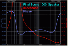
Most likely the distortion increase you are seeing at 10kHz is not from the ESL itself but from the driving amplifier or transformer. You can see that at 10kHz the impedance has dropped to less than 2 ohm. Almost all amplifiers have distortion profiles that increase with frequency above 1kHz and also increase when driving lower impedance.There are some other things that are funny. At 1 kHz / 90 dB, the 2nd harmonic is 60 dB down, at 10 kHz, it is only 50 dB down. If excursion was the problem, we'd expect it to get better at 10 kHz.

The transformer may also be contributing additional distortion at 10kHz if there is resistance in series with the primary.(pretty typical to have 1 – 2ohm). The increased current draw from the low impedance at 10kHz will result in more voltage drop across the resistance. If the current is distorted due to hysteresis effects, this distortion will show up in the voltage drop and thus passed on to the ESL stators.
This reduction is distortion is likely because 60Hz is approaching primary diaphragm resonance. Motion amplification at mechanical resonance is inherently low distortion which will compensate some for the increased distortion of the driving force.Similarly, at 100 Hz, 2nd and 3rd are 34 resp. 30 dB down, at 60 Hz (from the DIN IMD test), they are 38 and 47 dB down, again not what we would expect.
The hysteresis effect don't depend the load of secondary, only the max induction of core (this still remain same with or without secondary load). The Bmax is around a few mT at 10kHz, no more (at wide range trafo, of course). This means very small hysteresis induced distortion, especially the generator impedance of distortion's EMF is high (determined by major inductance of transformer)relative to driver's impedance, including series resistor.The increased current draw from the low impedance at 10kHz will result in more voltage drop across the resistance. If the current is distorted due to hysteresis effects, this distortion will show up in the voltage drop and thus passed on to the ESL stators.
Everytime I re-read that, and a few other contemporary -to -ESL, or the 'current-dumping amp' development papers PJB wrote with P Walker, I appreciate the same sense of admiration:Electrostatic Loudspeakers, Peter J. Baxandall; Chapter 3 in Loudspeaker and Headphone Handbook, John Borwick, Editor.
Jan
...wasn't Peter Baxandall a bloody genius!
His ability to address 'intuition' with deep analytic analysis; and then, very important, simply articulate & describe the thinking in a way anyone not on his level can read, was very special.
(&yes - I bought a copy of the 'Baxandall Papers' you published @jan.didden , on behalf of Doug Self. It remains an utter joy, too)
You are absolutely right!hysteresis effect don't depend the load of secondary, only the max induction of core
Thanks for the correction.
- Home
- Loudspeakers
- Planars & Exotics
- Inverted electrostat inferior in distortion?


