https://sound-au.com/project02.htm
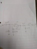
I'm using the final stage of Elliott's preamp
I'm using the final stage of Elliott's preamp
I'm using two 9 volt batteries.
My 10uf is Audyn Q4 from my 2way speaker Cross over.
Audiocap 3uf
Should I resolder all my joints?
Yes, and also monitor the signal after the input cap, and before the output cap.
DC offset was 143mv chanel a then went down to 12mv plugged it in and was fine for five minutes
I have 153mv at A out, .23mv at B out .
Assuming A and B are the op-amp output pins, the offset at A is too large, the offset at B is suspiciously small. 12 mV is in the right ballpark, considering the voltage drop that the input bias current of an NE5532 causes across 15 kohm and the gain.
Correction: actually -12 mV would be in the right ballpark. As the bias current flows into the NE5532 input pins, it causes a systematic negative offset when the + input sees a higher resistance than the - input.
Last edited:
As it is battery powered have you actually checked both supplies are OK when it fizzles and fades?
The 5532 has a relatively high current draw and will deplete batteries quicker than you might think. Measure the rails when the fault occurs. Also add some 100uF caps across each rail.
The 5532 has a relatively high current draw and will deplete batteries quicker than you might think. Measure the rails when the fault occurs. Also add some 100uF caps across each rail.
Bot
143mV is gross
I suspect path +IN>15k>Gnd is open, has terrible soldering, etc. leaving that OpAmp input floating and drifting.
Of course, this can/should be confirmed by measuring DC offset, both at +IN and output pin.
Ungrounded input will still take a few minutes to charge input cap so it may temporarily work confusing the symptoms.
Both are high if ground reference resistor is only 15kDC offset was 143mv chanel a then went down to 12mv plugged it in and was fine for five minutes
143mV is gross
I suspect path +IN>15k>Gnd is open, has terrible soldering, etc. leaving that OpAmp input floating and drifting.
Of course, this can/should be confirmed by measuring DC offset, both at +IN and output pin.
Ungrounded input will still take a few minutes to charge input cap so it may temporarily work confusing the symptoms.
As others have said, make sure you decouple the op-amp properly. Even if running on batteries, there is so much RF junk floating around that can get your op-amp oscillating that you need to deal with it properly.
Follow what Rod suggests in that project, putting the 0.1uF as close to the op-amp as possible:
Follow what Rod suggests in that project, putting the 0.1uF as close to the op-amp as possible:
Each op-amp should be bypassed with a 10µF/25V electrolytic from each supply lead to ground, and a 100nF capacitor between supply leads (not shown in diagrams). The latter should be as close as practicable to the op-amp supply pins, and the 10µF caps can be almost anywhere you like, but are best placed at the DC inputs.
- Home
- Amplifiers
- Solid State
- NE5532 preamp one channel cuts out after 5 minute
