Hi
I have a problem with the relay in this model and I don't know what could be the cause, but let's get to the point.
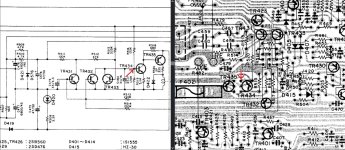
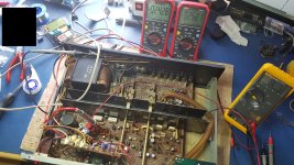
The amplifier starts up correctly and theoretically everything is OK, but within the first 10 minutes of operation the relay turns off and turns on again after a few seconds. This happens 2-4 times within 10 minutes and then everything is fine. The fault occurs mainly when the amplifier is not used for several hours, but this is not the rule. I corrected all the cold solder joints, and there were a lot of them. I checked the capacitors in the relay activation circuit and everything is OK. No DC voltage at the output before the relay. At the points marked with a red arrow there is approximately -12V, which holds the relay coil.
Sometimes the relay turns off and on when I stop the music.
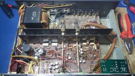
The photo shows that someone has already repaired this amplifier. He replaced power transistors and emitter resistors. He replaced the fuse resistors with ordinary resistors connected in parallel.
I'm asking for tips, because I have no idea where to look for the cause.
I have a problem with the relay in this model and I don't know what could be the cause, but let's get to the point.
The amplifier starts up correctly and theoretically everything is OK, but within the first 10 minutes of operation the relay turns off and turns on again after a few seconds. This happens 2-4 times within 10 minutes and then everything is fine. The fault occurs mainly when the amplifier is not used for several hours, but this is not the rule. I corrected all the cold solder joints, and there were a lot of them. I checked the capacitors in the relay activation circuit and everything is OK. No DC voltage at the output before the relay. At the points marked with a red arrow there is approximately -12V, which holds the relay coil.
Sometimes the relay turns off and on when I stop the music.
The photo shows that someone has already repaired this amplifier. He replaced power transistors and emitter resistors. He replaced the fuse resistors with ordinary resistors connected in parallel.
I'm asking for tips, because I have no idea where to look for the cause.
Attachments
Last edited:
Check by replacing C475 which is reservoir cap for the rail powering the relay circuit. It just has that 'look' about it and is a highly stressed part. C478 is another to replace.
Make sure the voltage at the junction of R513 and R514 really is close to zero when the fault occurs. If it reaches anywhere close to -/+0.5 volt then you have a problem with the amp circuits.
Your picture seems to show a clip missing of the vbe multiplier which should be held in thermal contact with the heatsink like the other channel.
Replacing also C479 and C480 would be a part of preventional hygiene.C478 is another to replace.
After that it makes sense to start tracing what goes on on the outputs but then the convenient tool would be a digital oscilloscope.
Caps 480 and 475 was replaced for the new one few days before my post here.
I replaced C479 now, but it didn't change. All these capacitors were replaced even though they had good capacity and low ESR.
Interestingly, I have already checked whether the DC voltage is present at the output before the relay and I may have connected it incorrectly because I did not notice any significant changes.
Today I connected to the points marked in the diagram with two voltmeters. When the voltage across them approaches -1VDC, the relay is cut off.
I guess there's a problem here.
Attachments
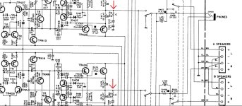
Speaker ground should be fine as long as you measure the actual output before the relay (as you mentioned you were doing).
1v on both channels is unusual and suggests something common to both. Normally an offset issue affects only one channel.
Monitor the voltage here on this regulator and check it does not vary. Also you mentioned some fuses that were actually resistors. They are shown as 100 ohm so worth checking they are correct value at least even if they are not fusible types fitted.
I checked the resistors you mentioned and others that my predecessor replaced. One of the ones you marked was 89 ohms instead of 100, and the 4.7 ohm resistors were 5.1. I replaced them all, but it didn't change anything.
I observed the voltage you mentioned +36VDC and it varies by 2VDC when amp play with dummy load, so it probably doesn't matter. At least that's what I think.
I observed the voltage you mentioned +36VDC and it varies by 2VDC when amp play with dummy load, so it probably doesn't matter. At least that's what I think.
Last edited:
It gets more difficult from here then and just to be clear, both channels are showing a DC offset that approaches 1 volt as measured from ground to each amp output before the relay.
The only other common rail I can see that could do this would be the supply to the LTP (long tailed pair) input stages.
Does this voltage vary as the fault develop? I'm not sure if you replaced the cap but also the two parallel resistors R509/510 could have a problem if one is going high in value. Check the voltage is stable.
There is also the negative supply to LTP (via FR407/408) - both of these supplies (to LTP) are unregulated and are fed via substantially different values of resistors. If the load (current through these resistors) changes then there difference between these rails may increase and result in the drift of the output.The only other common rail I can see that could do this would be the supply to the LTP (long tailed pair) input stages.
What are the voltages on these rails and how do they move during the failure buildup?
You could also measure the change in voltage drop across FR407 and 408 and also across R509/510 combo - that would show possible change in current consumption.
Maybe the similar voltage at the outputs is just coincidence. I can't help being suspicious of possible leakage in C439 and C440. They would provoke negative offset if defective; just 10mV of leakage (30uA) showing across R449 would generate -1V offset error. I suggest looking at drops across R449 and R450--- a simple measurement.
Good luck!
Good luck!
Does the other supply rail of the LTP vary in the same manner? If not then 1V output drift seems to correspond to 2V single rail drift?I observed the voltage you mentioned +36VDC and it varies by 2VDC when amp play with dummy load,
- Home
- Amplifiers
- Solid State
- Yamaha CA-V2 relay problem