Pfft. A link that returns a 404. Sigh.
Try https://docs.kicad.org/8.0/en/pcbnew/pcbnew.html#custom-design-rules
[Edit: the link probably does work for regular builds. It just doesn't work in development builds.]
Try https://docs.kicad.org/8.0/en/pcbnew/pcbnew.html#custom-design-rules
[Edit: the link probably does work for regular builds. It just doesn't work in development builds.]
First prototype boards are in, most parts are in, so building begins!

- Heater supply for the input tubes is built and works.
- Time delay for B+ and B- is built and seems to work (may need more testing).
- High-voltage supply for negative bias and buffer stage is built and works.
- B+ and B- supply is built, but not yet tested.
Attachments
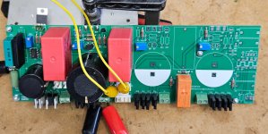
Finished building the PSU board. Received the Toroidy mains transformers and hooked them up. Works
I am not sure what's the best way to measure the high voltage of the stator bias. The internal resistance of the DVM pulls down the voltage immediately when I touch the HV pin. I might try charging a large capacitor to buffer the voltage and then take a reading off this.
I need to find a chassis to continue with a somewhat more self-contained prototype build. I don't feel comfortable with all that high voltage floating around the wire mess on my workbench...
A 10G HV resistor makes a nice 1000:1 attenuator with the 10M input resistance of most vanilla DVM.
Direct reading, 1KV = 1V.
This works well with the 6.5KV of the Quad ESL57.
The syringe is only for show.

I previously used a string of 10 or 22M resistors to make a 100:1 attenuator.
Direct reading, 1KV = 1V.
This works well with the 6.5KV of the Quad ESL57.
The syringe is only for show.
I previously used a string of 10 or 22M resistors to make a 100:1 attenuator.
Lots of prototyping and testing done during the past few days:
- Tested the BIAS supply voltage using the 10G resistor borrowed by @Zung. Voltage is 575 VDC, which is less than 1% off the 580 V target.
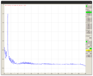
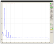
- Built and tested the input stage (with the tubes on the back of the PCB ). Works well. Output from the IPS goes up to 300 Vpp, where it starts clipping. Transients show no ringing. Output is flat up to 720 kHz (-6 dB). I attached screenshots of the harmonic spectra at 1 Vrms and 10 Vrms output.
- Built and tested the Coleman DHT Filament regulators. They work as expected running off a bench PSU. Still need to make the raw DC supplies for the Coleman boards.
- The buffer stage does not yet work. I messed up the circuit and the pinout of the FETs in the buffer stage right before sending out the gerbers for PCB manufacturing. It took me a while to figure out these problems. I also had a few hickups due to probe slips and brain malfunction, killing the pass devices on the HV supplies a few times, and even a 6E5P tube .
Attachments
- Home
- Amplifiers
- Headphone Systems
- Open Source DHT Estat Headphone Amp -- OSDEHA