No stuffing errors to be found. Running out of options.
S stephan-schulz Member Joined 2008 2024-04-02 8:02 pm #4,481 No stuffing errors to be found. Running out of options.
A as_audio Member Joined 2008 2024-04-02 8:03 pm #4,482 We need clear pictures of both sides of the pcb.
A as_audio Member Joined 2008 2024-04-02 8:06 pm #4,484 I see a solder bridge on BC337 near to the wired output, picture of post 4461.
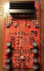
S stephan-schulz Member Joined 2008 2024-04-02 8:15 pm #4,485 Here are the pictures. pls bear in mind that i bought this project half started so not all soldering has been done by myself. Attachments IMG_0011.jpeg 546.9 KB · Views: 49
Here are the pictures. pls bear in mind that i bought this project half started so not all soldering has been done by myself.
A as_audio Member Joined 2008 2024-04-02 8:20 pm #4,488 4485 : soldering looks like a mess. Bad layout, miniature copper eye sizes and poor mask design are the reason.
4485 : soldering looks like a mess. Bad layout, miniature copper eye sizes and poor mask design are the reason.
A as_audio Member Joined 2008 2024-04-02 8:22 pm #4,489 Did you use silver solder ? For a board like this the old style lead type is preferred.
S stephan-schulz Member Joined 2008 2024-04-02 8:46 pm #4,490 as_audio said: I see a solder bridge on BC337 near to the wired output, picture of post 4461. Click to expand... Removed. No changes. Was almost impossible to solder some of the eyes. Boards are from 2012 as far as I know. All will go into the bin. Worst project ever. Lesson learned: Never buy half started projects from people you dont know. Thank you all for your great support.
as_audio said: I see a solder bridge on BC337 near to the wired output, picture of post 4461. Click to expand... Removed. No changes. Was almost impossible to solder some of the eyes. Boards are from 2012 as far as I know. All will go into the bin. Worst project ever. Lesson learned: Never buy half started projects from people you dont know. Thank you all for your great support.
A as_audio Member Joined 2008 2024-04-02 9:12 pm #4,492 Do not throw them away. It is not likely that the solder bridge caused any additional harm, but semiconductors in the area can be easily checked in place. It is highly likely that you can find other soldering errors.
Do not throw them away. It is not likely that the solder bridge caused any additional harm, but semiconductors in the area can be easily checked in place. It is highly likely that you can find other soldering errors.
A as_audio Member Joined 2008 2024-04-02 9:16 pm #4,493 Looking at the copper side I see more issues. Have a close look at all three-legged components. It even seems one connection is missing the copper tab. Otherwise : let me be your waste bin. I fixed a lot like these.
Looking at the copper side I see more issues. Have a close look at all three-legged components. It even seems one connection is missing the copper tab. Otherwise : let me be your waste bin. I fixed a lot like these.
A as_audio Member Joined 2008 2024-04-02 9:24 pm #4,494 Photographic angle of the component side does not allow solder inspection. Remove excess flux on the copper side with solvent and toothbrush. Remove excessive solder and reflow in certain places. I had a short look only :
Photographic angle of the component side does not allow solder inspection. Remove excess flux on the copper side with solvent and toothbrush. Remove excessive solder and reflow in certain places. I had a short look only :
S stephan-schulz Member Joined 2008 2024-04-02 9:27 pm #4,495 Ok guys! One final attempt to save the world 😂! when Soccer (Saarbrücken vs Kaiserslautern) is over i‘ll resolder everything suspicious.
Ok guys! One final attempt to save the world 😂! when Soccer (Saarbrücken vs Kaiserslautern) is over i‘ll resolder everything suspicious.
A as_audio Member Joined 2008 2024-04-02 9:32 pm #4,496 Too much solder in many places. With small size copper eyes like these it is advisable to clip the leads first and solder later.
Too much solder in many places. With small size copper eyes like these it is advisable to clip the leads first and solder later.
A as_audio Member Joined 2008 2024-04-02 9:40 pm #4,497 hesener said: Paradise is a transimpedance amplifier .. Click to expand... No, it is not.
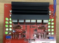
S stephan-schulz Member Joined 2008 2024-04-02 11:09 pm #4,498 cleaned up the soldering and now everything works. (luckily i will solder the other board all by myself.) With 10k parallel to the input I was able to adjust the voltage on the input to 0V, output being close to 0V aswell. Attachments IMG_0013.jpeg 680.5 KB · Views: 26
cleaned up the soldering and now everything works. (luckily i will solder the other board all by myself.) With 10k parallel to the input I was able to adjust the voltage on the input to 0V, output being close to 0V aswell.