Syn08 (Ovidiu) said this about implementing an Auto Bias loop here:
Well, there's the challenge. A wideband non switching Auto Bias amplifier circuit that works, doesn't oscillate and blow up, and is not too complex.
To start this thread I'll post some of my findings from simulations of the LT1166 Auto Bias IC, as well as Class-i and Edmond's AutoBias2.
Feel free to post any of your ideas and simulations.
And if anyone has built a successful amplifier using an auto bias circuit then we'd love to hear how you did it, etc.
Cheers, Ian
-------------
Edit: Some circuits:
Post 3 Syn08 LT1166 + HV opamp LM4702, LM4702 app Top/Bottom drive with Darlington's. Breadboarded 28KHz BW. Not datasheet version. Like Post 20.
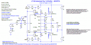
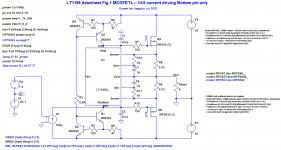
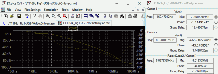
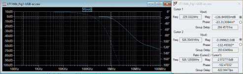
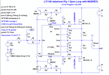
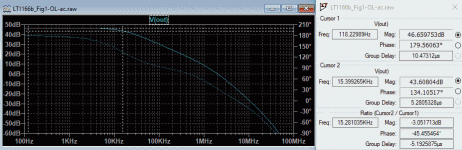
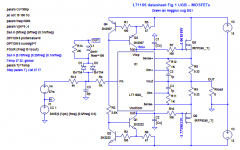
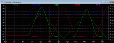
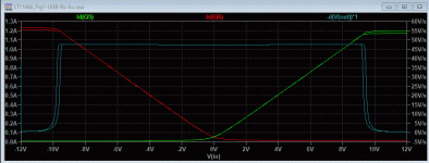
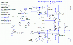
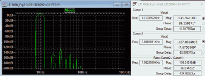
Post 5 Type A: LT1166 Top/Bottom pin driven open loop voltage gain is 47dB, BW 15kHz. (Post 2 UGB version 8kHz BW with current source drive to Top/Bottom pins.)
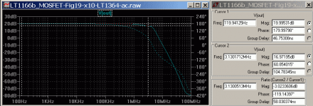
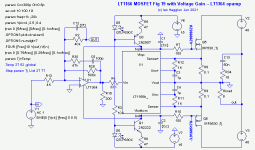
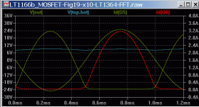
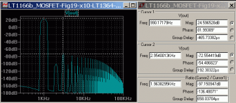
Post 6 Voltage Gain Topology, LV opamp Top/Bottom pin driven, gain 20dB, ss-BW 3MHz. THD 0.002%. Post 27 shows slew limiting, OK up to 300kHz.
Post 11 Marcel van de Gevel links to his published and successful auto bias amplifier EW+WW Feb 1996. BW 140KHz, THD 0.006%. Has a cross-conduction crowbar (Q19,Q20) to trigger speaker relay. Ingenious non-complement design with a CA3046 array.
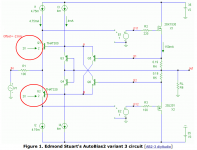
Post 14 Edmond Stuart's AutoBias2 circuit.
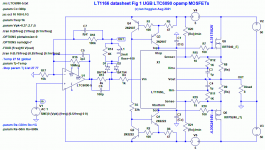
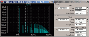
Post 20 Type B: HV opamp LT6090 Vin pin driven, ±50V 100W, SR 17V/us due to opamp OK to 50kHz. THD 0.0001% 100W and 0.000015% 1W.
Post 37 The LTspice library LT1166 model.
Post 45 Peufeu auto bias and non-switching basic circuit using Schottky diodes in place of source resistors as peufeu's thread here like the E Van Drecht patent. See Post 65.
Post 52 Syn08 Non-switching MOSFET 500W/4ohm, THD 0.0005%. No bias loop, CFP keep-on current, CFP uses current mirrors.
Post 53 Syn08 Simpler non-switching MOSFET, ±15V LME49710, No bias loop, CFP keep-on current, CFP with voltage gain uses current mirrors.
Post 65 CFA diamond splitter, output stage with voltage gain, Non-switching Rush Vbe multiplier coupled to Schottky diodes in the MOSFET sources (See Post 45).
Post 78 Comparison of a 4mR RDSon MOS-diode with a 10A Schottky diode show similar volt drop at 10A but temperature coefficient is negative for Schottky (results in thermal runaway in an autobias loop) and MOS-diode has a positive temp-co. (thermally safe in an autobias loop).
Post 90 Similar to Post 65 Vbe multiplier coupled to Schottky diodes in the MOSFET sources, but now Autobias by adding two current sources to add some DC voltage to the Schottky diodes allowing the trimpot to be eliminated. Once the current sources are carefully set you can change the power MOSFETs to BJTs and the idle current is almost the same -- thanks to the Autobias feedback loop. Q.E.D.
Post 93 Replace Schottky diodes with MOS-diodes. No Vbe multiplier feedback resistor used. No need to thermally couple the spreader to the power transistors. Autobias MOS-diodes keep the idle/crossover current much more stable than Schottky's.
Post 99 using IGBTs with autobias MOS-diodes. Changing to IGBTs gives about the same idle current without changing the bias settings -- thanks to the Autobias feedback loop. Sim'd THD doesn't change much no matter what power devices are used") .
.
Post 105 All the autobias versions thus far are in one attached file including the latest versions of the electrothermal subcircuits. A tutorial for using these electrothermal 'widgets' with demo jigs is at my website.
Post 111 Pass F4 variant: Class-A buffer with autobias, 200W 4 ohms. Needs high level drive (40Vpk) preamp.
Post 115 Pass F4 variant: Class-A with autobias as a transconductance amplifier with gain, soft-clip, 200W 4 ohms, 0.001% 1W.
Post 116 Pass F4 variant: Class-A balanced bridge, autobias transconductance amplifier with gain, soft-clip, 100W 8 ohms, 0.001% 1W.
Post 135 bench tests with parallel IRF540N and MOS-diodes using the same. Good current sharing. Good linearity with 400mA bias. Over-compensation required thicker thermal washers for the MOS-diodes.
Post 137 bench tests with parallel IRF540N and two 10A Schottky diodes (instead of MOS-diodes). Current sharing resistors required. Good linearity with 400mA bias. Over-compensation required thicker thermal washers for the Schottky diodes.
Post 138 best thermal compensation so far with one of the autobias spreader transistors on one Schottky diode, the other spreader transistor at ambient to halve the temp.co ( now just right). Slice paralleling best as per LT1166 application note.
Post 141 Re design aims: minimalism and no source resistors. Ultra low THD is not necessary with no source resistors due to mainly low order harmonics up to 1W or so (thanks to the higher bias current for minimum distortion).
Post 150 bench test with MJL3281/1302 instead of MOSFETs. Good performance. Lower optimum bias with BJT's in place of MOSFETs.
Post 156 Bipolar power transistors without Darlington drivers as per E Van Drecht autobias patent and floating voltage offset for bias as peufeu Post 393.
Post 157 2 channel listening test with only 6dB voltage feedback, single 43V floating supply, sounds great and doesn't blow up. It works!
Post 158 Similar to Post 157 but with a diamond driver allowing higher input resistance of 10k but now requires compensation for stability (for when the input is open circuit). More voltage feedback gives lower output resistance. A zero feedback topology with very little local feedback - that's very rare.
Post 160 For those who want a non-floating standard power supply. LT6090-5 high voltage opamp - but it's not a fast opamp - sorry. BTW the floating supply versions above are not slew rate limited, only BW limited, so is the best option IMHO. Just parallel slices with higher voltage rails to get more power.
" I haven't see a solid non switching full solution for the entire audio band, but only partial improvements over the standard solution of an acceleration cap (100nF, in your case), which is not a solution for non switching, but only a bandaid to limit the effect of the crossover mess.
Part of this lack of solutions is of course keeping the complexity within reasonable limits; Edmond's solution mentioned above, in despite of it's stability issues, is already a rather complex circuit, and I don't think anything simpler could be designed and successfully implemented."
Well, there's the challenge. A wideband non switching Auto Bias amplifier circuit that works, doesn't oscillate and blow up, and is not too complex.
To start this thread I'll post some of my findings from simulations of the LT1166 Auto Bias IC, as well as Class-i and Edmond's AutoBias2.
Feel free to post any of your ideas and simulations.
And if anyone has built a successful amplifier using an auto bias circuit then we'd love to hear how you did it, etc.
Cheers, Ian
-------------
Edit: Some circuits:
Post 3 Syn08 LT1166 + HV opamp LM4702, LM4702 app Top/Bottom drive with Darlington's. Breadboarded 28KHz BW. Not datasheet version. Like Post 20.
Post 5 Type A: LT1166 Top/Bottom pin driven open loop voltage gain is 47dB, BW 15kHz. (Post 2 UGB version 8kHz BW with current source drive to Top/Bottom pins.)
Post 6 Voltage Gain Topology, LV opamp Top/Bottom pin driven, gain 20dB, ss-BW 3MHz. THD 0.002%. Post 27 shows slew limiting, OK up to 300kHz.
Post 11 Marcel van de Gevel links to his published and successful auto bias amplifier EW+WW Feb 1996. BW 140KHz, THD 0.006%. Has a cross-conduction crowbar (Q19,Q20) to trigger speaker relay. Ingenious non-complement design with a CA3046 array.
Post 14 Edmond Stuart's AutoBias2 circuit.
Post 20 Type B: HV opamp LT6090 Vin pin driven, ±50V 100W, SR 17V/us due to opamp OK to 50kHz. THD 0.0001% 100W and 0.000015% 1W.
Post 37 The LTspice library LT1166 model.
Post 45 Peufeu auto bias and non-switching basic circuit using Schottky diodes in place of source resistors as peufeu's thread here like the E Van Drecht patent. See Post 65.
Post 52 Syn08 Non-switching MOSFET 500W/4ohm, THD 0.0005%. No bias loop, CFP keep-on current, CFP uses current mirrors.
Post 53 Syn08 Simpler non-switching MOSFET, ±15V LME49710, No bias loop, CFP keep-on current, CFP with voltage gain uses current mirrors.
Post 65 CFA diamond splitter, output stage with voltage gain, Non-switching Rush Vbe multiplier coupled to Schottky diodes in the MOSFET sources (See Post 45).
Post 78 Comparison of a 4mR RDSon MOS-diode with a 10A Schottky diode show similar volt drop at 10A but temperature coefficient is negative for Schottky (results in thermal runaway in an autobias loop) and MOS-diode has a positive temp-co. (thermally safe in an autobias loop).
Post 90 Similar to Post 65 Vbe multiplier coupled to Schottky diodes in the MOSFET sources, but now Autobias by adding two current sources to add some DC voltage to the Schottky diodes allowing the trimpot to be eliminated. Once the current sources are carefully set you can change the power MOSFETs to BJTs and the idle current is almost the same -- thanks to the Autobias feedback loop. Q.E.D.
Post 93 Replace Schottky diodes with MOS-diodes. No Vbe multiplier feedback resistor used. No need to thermally couple the spreader to the power transistors. Autobias MOS-diodes keep the idle/crossover current much more stable than Schottky's.
Post 99 using IGBTs with autobias MOS-diodes. Changing to IGBTs gives about the same idle current without changing the bias settings -- thanks to the Autobias feedback loop. Sim'd THD doesn't change much no matter what power devices are used
.Post 105 All the autobias versions thus far are in one attached file including the latest versions of the electrothermal subcircuits. A tutorial for using these electrothermal 'widgets' with demo jigs is at my website.
Post 111 Pass F4 variant: Class-A buffer with autobias, 200W 4 ohms. Needs high level drive (40Vpk) preamp.
Post 115 Pass F4 variant: Class-A with autobias as a transconductance amplifier with gain, soft-clip, 200W 4 ohms, 0.001% 1W.
Post 116 Pass F4 variant: Class-A balanced bridge, autobias transconductance amplifier with gain, soft-clip, 100W 8 ohms, 0.001% 1W.
Post 135 bench tests with parallel IRF540N and MOS-diodes using the same. Good current sharing. Good linearity with 400mA bias. Over-compensation required thicker thermal washers for the MOS-diodes.
Post 137 bench tests with parallel IRF540N and two 10A Schottky diodes (instead of MOS-diodes). Current sharing resistors required. Good linearity with 400mA bias. Over-compensation required thicker thermal washers for the Schottky diodes.
Post 138 best thermal compensation so far with one of the autobias spreader transistors on one Schottky diode, the other spreader transistor at ambient to halve the temp.co ( now just right). Slice paralleling best as per LT1166 application note.
Post 141 Re design aims: minimalism and no source resistors. Ultra low THD is not necessary with no source resistors due to mainly low order harmonics up to 1W or so (thanks to the higher bias current for minimum distortion).
Post 150 bench test with MJL3281/1302 instead of MOSFETs. Good performance. Lower optimum bias with BJT's in place of MOSFETs.
Post 156 Bipolar power transistors without Darlington drivers as per E Van Drecht autobias patent and floating voltage offset for bias as peufeu Post 393.
Post 157 2 channel listening test with only 6dB voltage feedback, single 43V floating supply, sounds great and doesn't blow up. It works!
Post 158 Similar to Post 157 but with a diamond driver allowing higher input resistance of 10k but now requires compensation for stability (for when the input is open circuit). More voltage feedback gives lower output resistance. A zero feedback topology with very little local feedback - that's very rare.
Post 160 For those who want a non-floating standard power supply. LT6090-5 high voltage opamp - but it's not a fast opamp - sorry
. BTW the floating supply versions above are not slew rate limited, only BW limited, so is the best option IMHO. Just parallel slices with higher voltage rails to get more power.
Last edited: