I'm sharing my design/code of an Arduino-based tube amp control system. Code and photo are attached. Here are the things it does:
1. Fault monitoring. It continuously checks for fault conditions (e.g. tube over power, HV too high, etc.) and immediately shuts the amp down if one occurs.
2. Display current conditions. I have it displaying plate voltages for input tubes, output tube plate currents and powers, B+ voltage, and tube hours.
3. Bias tubes. I have it set up to bias my input tubes by adjusting screen voltage and bias output tubes the usual way, but my amp is an A2 amp so grid bias is a positive voltage.
Hardware Description
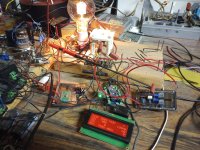
Let me walk through the photo. I'm not going to bother making a schematic but everything is simple enough if you follow instructions/documentation from Arduino and Adafruit.
In the middle is the Arduino Nano Every with an Adafruit MCP4728 four-channel DAC daughter board. You don't need the DAC if you don't want tube bias under microcontroller control.
On the left of the Arduino is a prototype board with a HV amp chip so that the DAC outputs can get scaled up to the voltages I need for biasing the tubes (~100V for the input tubes and ~35V for the output tubes). My particular amp needs positive bias voltages so I am using an HV264 chip, but you would probably need some sort of inverting HV op-amp setup to get negative voltages and you would need to modify the code to make sure it moves the right direction to increase/decrease tube operating conditions and that the gains it uses to calculate changes are correct. It's flexible but you definitely want to run some tests before you hook it up to a real tube.
Additionally, on that board to the left you can see a 7805 regulator and behind it an IRL520 which is used as an open-drain output to drive the SSR that controls the main AC power input for the amplifier. That's what the Arduino uses to shut things down if a fault condition is detected. Obviously, for this to work the Arduino will have to be always powered and it is in control of the rest of the power.
Mounted to the board above the Arduino are all of the voltage dividers that I use to sample B+ and the plate voltages of the input tube. I do filter audio frequencies from output of that divider so the Arduino is not sampling instantaneous plate voltage of the input tube but average voltage. I do the same for output tube plate current sampling.
The board on the right (and the black brick next to the Arduino) is all circuitry that I use to sense plate current. Most amps don't need any of that because cathode current sensing is much easier and simpler. I needed to do high-side plate current sensing because this A2 amp has both grid current and plate current in the cathode current, so I needed to measure plate current alone. I used a TLP7920 and a bunch of supporting circuitry to do that.
The display is a "RGB backlight negative LCD 20x4 + extras (RGB on black) [ID:498]" from Adafruit also using the "i2c / SPI character LCD backpack[ID:292]". Anything you want to display can be displayed there. As you can see I'm displaying B+, input tube plate voltage, and output tube plate currents and powers, and I have an hours meter for the output tubes.
It is so nice to have a display like this that gives you a bunch of measurements at a glance when you are experimenting (especially with transmitting tube B+ voltages). All of my future work is going to be done like this.
Software Description
I'll just do a very high level description of the software.
All functions are non-blocking. They check and see if work is ready to be done. If not, they return immediately with the expectation that they will be called again when the work is ready.
The program has three main states: AMPLIFIER_OFF, AMPLIFIER_WARMUP, and AMPLIFIER_ON. The main loop simply calls the associated main task for each state.
The amplifier off task simply updates the heartbeat LED and waits for the power button to be pressed.
The amplifier warmup task initializes DAC outputs, sets up the display, turns on the AC power to the amp and then runs a countdown timer on the display so that the user knows when amp is ready. It also starts bias adjustments on any tubes that are past their warmup time, checks for fault conditions, and keeps the heartbeat LED going.
The amplifier on task reads ADCs and updates the display, checks for faults, biases the tubes, and keeps the heartbeat LED going.
Upon shutdown, the processor stores the last good bias values in EEPROM and uses them as initial values on the next startup.
The header file contains many values that can be configured for the particular tubes used and other settings. I have it set to slowly ramp voltage on bias adjustments over a period of 5 seconds and adjust every 30 seconds. There are a lot of tube specific settings for the bias control in the header file.
The code is set to check for a bias button to be pressed to initiate the bias adjustment process. I simply wired it to GND for it to bias every 30 seconds.
Code is less than 1000 lines total.
One last note about sampling current/voltage: The amp I made this for was class A SE. I did some experiments to see if I needed to wait for musical silence to do the calculations to make bias adjustments. Basically, I played loud electronic music with sustained bass notes and I paused and un-paused while I watched to see if that would perturb any of the voltages/currents on the display. None of the values seemed to change at all on this amp, so I made the decision to just adjust bias whenever. If you are going to use it on a push-pull AB amp, I'd run a similar experiment. If it turns out that the average current changes by an amount that makes you uncomfortable, I'd implement a silence detection circuit that hits that bias button input every time there is silence. Then all of the calculations will be based on low/no signal conditions.
1. Fault monitoring. It continuously checks for fault conditions (e.g. tube over power, HV too high, etc.) and immediately shuts the amp down if one occurs.
2. Display current conditions. I have it displaying plate voltages for input tubes, output tube plate currents and powers, B+ voltage, and tube hours.
3. Bias tubes. I have it set up to bias my input tubes by adjusting screen voltage and bias output tubes the usual way, but my amp is an A2 amp so grid bias is a positive voltage.
Hardware Description
Let me walk through the photo. I'm not going to bother making a schematic but everything is simple enough if you follow instructions/documentation from Arduino and Adafruit.
In the middle is the Arduino Nano Every with an Adafruit MCP4728 four-channel DAC daughter board. You don't need the DAC if you don't want tube bias under microcontroller control.
On the left of the Arduino is a prototype board with a HV amp chip so that the DAC outputs can get scaled up to the voltages I need for biasing the tubes (~100V for the input tubes and ~35V for the output tubes). My particular amp needs positive bias voltages so I am using an HV264 chip, but you would probably need some sort of inverting HV op-amp setup to get negative voltages and you would need to modify the code to make sure it moves the right direction to increase/decrease tube operating conditions and that the gains it uses to calculate changes are correct. It's flexible but you definitely want to run some tests before you hook it up to a real tube.
Additionally, on that board to the left you can see a 7805 regulator and behind it an IRL520 which is used as an open-drain output to drive the SSR that controls the main AC power input for the amplifier. That's what the Arduino uses to shut things down if a fault condition is detected. Obviously, for this to work the Arduino will have to be always powered and it is in control of the rest of the power.
Mounted to the board above the Arduino are all of the voltage dividers that I use to sample B+ and the plate voltages of the input tube. I do filter audio frequencies from output of that divider so the Arduino is not sampling instantaneous plate voltage of the input tube but average voltage. I do the same for output tube plate current sampling.
The board on the right (and the black brick next to the Arduino) is all circuitry that I use to sense plate current. Most amps don't need any of that because cathode current sensing is much easier and simpler. I needed to do high-side plate current sensing because this A2 amp has both grid current and plate current in the cathode current, so I needed to measure plate current alone. I used a TLP7920 and a bunch of supporting circuitry to do that.
The display is a "RGB backlight negative LCD 20x4 + extras (RGB on black) [ID:498]" from Adafruit also using the "i2c / SPI character LCD backpack[ID:292]". Anything you want to display can be displayed there. As you can see I'm displaying B+, input tube plate voltage, and output tube plate currents and powers, and I have an hours meter for the output tubes.
It is so nice to have a display like this that gives you a bunch of measurements at a glance when you are experimenting (especially with transmitting tube B+ voltages). All of my future work is going to be done like this.
Software Description
I'll just do a very high level description of the software.
All functions are non-blocking. They check and see if work is ready to be done. If not, they return immediately with the expectation that they will be called again when the work is ready.
The program has three main states: AMPLIFIER_OFF, AMPLIFIER_WARMUP, and AMPLIFIER_ON. The main loop simply calls the associated main task for each state.
The amplifier off task simply updates the heartbeat LED and waits for the power button to be pressed.
The amplifier warmup task initializes DAC outputs, sets up the display, turns on the AC power to the amp and then runs a countdown timer on the display so that the user knows when amp is ready. It also starts bias adjustments on any tubes that are past their warmup time, checks for fault conditions, and keeps the heartbeat LED going.
The amplifier on task reads ADCs and updates the display, checks for faults, biases the tubes, and keeps the heartbeat LED going.
Upon shutdown, the processor stores the last good bias values in EEPROM and uses them as initial values on the next startup.
The header file contains many values that can be configured for the particular tubes used and other settings. I have it set to slowly ramp voltage on bias adjustments over a period of 5 seconds and adjust every 30 seconds. There are a lot of tube specific settings for the bias control in the header file.
The code is set to check for a bias button to be pressed to initiate the bias adjustment process. I simply wired it to GND for it to bias every 30 seconds.
Code is less than 1000 lines total.
One last note about sampling current/voltage: The amp I made this for was class A SE. I did some experiments to see if I needed to wait for musical silence to do the calculations to make bias adjustments. Basically, I played loud electronic music with sustained bass notes and I paused and un-paused while I watched to see if that would perturb any of the voltages/currents on the display. None of the values seemed to change at all on this amp, so I made the decision to just adjust bias whenever. If you are going to use it on a push-pull AB amp, I'd run a similar experiment. If it turns out that the average current changes by an amount that makes you uncomfortable, I'd implement a silence detection circuit that hits that bias button input every time there is silence. Then all of the calculations will be based on low/no signal conditions.
")