Hello Community,
I am working on learning about crossover design. I am currently rebuilding a set of Cerwin Vega! L7 Bookshelf speakers. I purchased the set at Goodwill for around US$25. I am cutting out the baffles and will make new ones from 3/4" MDF. I have not chosen any drivers or crossover components.
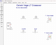
I have the original crossovers and want to understand how to reverse engineer them back to basic diagrams. I have included photos of the front and back and a basic Xsim work up. I need help understanding how to turn the photos into a diagram. I have no understanding of which ends of each components relates to the positive and ground network.
Anu help would be much appreciated.
George
I am working on learning about crossover design. I am currently rebuilding a set of Cerwin Vega! L7 Bookshelf speakers. I purchased the set at Goodwill for around US$25. I am cutting out the baffles and will make new ones from 3/4" MDF. I have not chosen any drivers or crossover components.
I have the original crossovers and want to understand how to reverse engineer them back to basic diagrams. I have included photos of the front and back and a basic Xsim work up. I need help understanding how to turn the photos into a diagram. I have no understanding of which ends of each components relates to the positive and ground network.
Anu help would be much appreciated.
George
Attachments
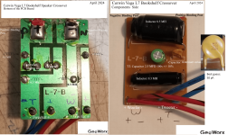

Thank you. I'm guessing that is to stop the speaker from "blowing" if the amp it is hooked up to is too powerful for the speaker.The disc device would be a polyswitch, assume it is like a fusible link. The tweeter uses the capacitor and larger inductor as a 2nd order filter, and has reversed polarity. The woofer uses the smaller inductor.
Thank you, I will see how that works on the crossover and see if I can draw out a similar circuit.this is the schematic diagram:
A powerful amplifier won't hurt your tweeters unless you tell it to with your volume setting. In fact, low powered amps are more risky to tweeters because of the distortion when you turn them up too far.I'm guessing that is to stop the speaker from "blowing" if the amp it is hooked up to is too powerful for the speaker.