I received an early version Cambridge Audio/AR P35 recently for free as it was supposedly non-working - the power LED didn't light up. A quick check-over with a DVM confirmed it was in fact working and it sounded quite good for a 1984 35W amplifier. There is not much info about these amps (and no, I don't have a circuit schematic either!) but I believe it was a special design of the Cambridge Audio P35 by Stan Curtis which was manufactured by Cambridge Audio. Anyway, I thought it was well worth giving it a refurb to make sure it lasted another 33 years!
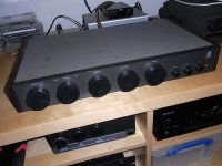
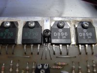
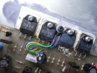
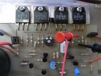
Lifting the lid was a revelation. It looked like an early lab prototype with one or two design "issues". The obvious problem was the output stage current set TO-92 bias transistors were not attached to the heatsink, for optimum thermal tracking. The right channel bias transistor was worse, only barely coupled onto the legs of one of the power transistors. This was probably the reason the bias setting across output stage 0.5R emitter resistors was set less than 1mV on all transistors.
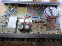
I found the easiest way to work on this amplifier was to remove the two printed circuit boards and toroidal transformer from the panels and base-plate. The printed circuit boards can be safely turned over together to reveal the copper track side, taking care not to over-stress the grey flat ribbon connector between the Phono pre-amp and the power amplifier.
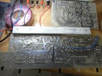
The left channel bias transistor was easy to mount onto the aluminium heatsink bar, between the output stage power transistors, using a washer and M3 self-tapper. The right channel bias transistor was a bit more of a challenge, and had to have extended leads to allow it to be fitted between the output stage power transistors. At the same time, I removed the 2K2 bias potentiometer and remounted it facing outwards to allow adjustment underneath the ribbon cable connection.
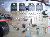
When I investigated the non-working Power On LED, the LED was connected reverse polarity by someone who had attempted a repair and not diagnosed the real fault the 3K9 1/4W dropper resistor had gone open-circuit. It probably didn't like being slow-cooked at 1/2W over the last 30 years so it was replaced with a 1W version.
The TL072 op-amp gain stage before the 47K volume control had no power supply decoupling capacitors on the + and - supply pins and was also set at around 18.5V each rail, exceeding its maximum supply rating. I removed the op-amp and fitted a DIL socket and 22uF/100nF decoupling caps to each supply. The op-amp was replaced by an OP275 which is good for up to 22V. Apart from the 6800uF PSU ripple capacitors, there were no other HT rail decoupling capacitors around the board so I fitted 4off 220uF evenly across the board. Finally, I replaced the existing small electrolytics with same value.
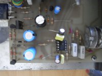
I re-assembled the boards and transformer onto the base-plate and checked over everything before powering up. With the DVM across the output stage 0.5R emitter resistor (2 x 1R in parallel), I adjusted the bias potentiometer to between 10 - 15mV, giving approx. 20 - 30mA per output stage power transistor. The thermal tracking seemed to be working very well and the bias voltage was falling gradually as the power transistors heated up.
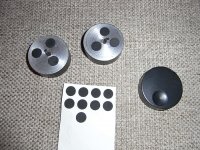
The final tidy-up was to put felt pads onto the back of the front panel rotary dials so they can be pushed back firmly onto the potentiometer spindles and sit flat against the panel. After several hours playing at reasonably high volume, I noticed the output stage transistors on aluminium heatsink were much hotter than was probably good for their long-term reliability. The aluminium heatsink should have been much larger to spread the heat better to improve cooling but things were not being helped by the very short rubber mounting feet that restricted convection cooling underneath the metal base-plate. I added 4off 20mm plastic feet to raise the amplifier base above the mounting surface and this improved cooling considerably.
Does it sound any better? I don't know, I only listened to it briefly initially but it sounds pretty good to me and is now getting plenty of air play. It could easily shame some much more recently released "hi-fi" audio amplifiers

Lifting the lid was a revelation. It looked like an early lab prototype with one or two design "issues". The obvious problem was the output stage current set TO-92 bias transistors were not attached to the heatsink, for optimum thermal tracking. The right channel bias transistor was worse, only barely coupled onto the legs of one of the power transistors. This was probably the reason the bias setting across output stage 0.5R emitter resistors was set less than 1mV on all transistors.

I found the easiest way to work on this amplifier was to remove the two printed circuit boards and toroidal transformer from the panels and base-plate. The printed circuit boards can be safely turned over together to reveal the copper track side, taking care not to over-stress the grey flat ribbon connector between the Phono pre-amp and the power amplifier.

The left channel bias transistor was easy to mount onto the aluminium heatsink bar, between the output stage power transistors, using a washer and M3 self-tapper. The right channel bias transistor was a bit more of a challenge, and had to have extended leads to allow it to be fitted between the output stage power transistors. At the same time, I removed the 2K2 bias potentiometer and remounted it facing outwards to allow adjustment underneath the ribbon cable connection.


When I investigated the non-working Power On LED, the LED was connected reverse polarity by someone who had attempted a repair and not diagnosed the real fault the 3K9 1/4W dropper resistor had gone open-circuit. It probably didn't like being slow-cooked at 1/2W over the last 30 years so it was replaced with a 1W version.
The TL072 op-amp gain stage before the 47K volume control had no power supply decoupling capacitors on the + and - supply pins and was also set at around 18.5V each rail, exceeding its maximum supply rating. I removed the op-amp and fitted a DIL socket and 22uF/100nF decoupling caps to each supply. The op-amp was replaced by an OP275 which is good for up to 22V. Apart from the 6800uF PSU ripple capacitors, there were no other HT rail decoupling capacitors around the board so I fitted 4off 220uF evenly across the board. Finally, I replaced the existing small electrolytics with same value.

I re-assembled the boards and transformer onto the base-plate and checked over everything before powering up. With the DVM across the output stage 0.5R emitter resistor (2 x 1R in parallel), I adjusted the bias potentiometer to between 10 - 15mV, giving approx. 20 - 30mA per output stage power transistor. The thermal tracking seemed to be working very well and the bias voltage was falling gradually as the power transistors heated up.


The final tidy-up was to put felt pads onto the back of the front panel rotary dials so they can be pushed back firmly onto the potentiometer spindles and sit flat against the panel. After several hours playing at reasonably high volume, I noticed the output stage transistors on aluminium heatsink were much hotter than was probably good for their long-term reliability. The aluminium heatsink should have been much larger to spread the heat better to improve cooling but things were not being helped by the very short rubber mounting feet that restricted convection cooling underneath the metal base-plate. I added 4off 20mm plastic feet to raise the amplifier base above the mounting surface and this improved cooling considerably.
Does it sound any better? I don't know, I only listened to it briefly initially but it sounds pretty good to me and is now getting plenty of air play. It could easily shame some much more recently released "hi-fi" audio amplifiers
Attachments
Last edited:
Hi Jaycee, very tempting I'm sure! But then you would have built a totally different amplifier and changed its characteristic sound completely. Most of the parts in these vintage amplifiers are now obsolete and irreplaceable. We should just sit back and enjoy the rich mellow, vintage sound in the same way that others still go to museums to look at the skeletons of long lost dinosaurs
I don't think roclite referred to the speaker outputs anywhere. However, he does describe adding extra decoupling capacitors to the output stage power rails by fitting new 220uF capacitors between the rail and power supply ground locally. You can see this marked on the PCB in the pics and by suitably spaced new holes and leads poking through the underside.
He also describes using the output stage emitter resistors as a point to measure Vre, the (paralleled) emitter resistor voltage drop. It's a routine bias setting procedure applying to most power amplifiers with a few points to note here about parallel arrangements.
He also describes using the output stage emitter resistors as a point to measure Vre, the (paralleled) emitter resistor voltage drop. It's a routine bias setting procedure applying to most power amplifiers with a few points to note here about parallel arrangements.
Thanks for your reply Ian, the problem i have is that on first turn on there is a loud arcing sound on the speakers for about a second or so then all is well. This i guess is a momentary dc pulse which is heard through the speakers. I can't find anything wrong with the unit so am thinking it's due to the simplistic design? I was considering fitting a thermistor on the ac input line, any suggestions? Perhaps Roclite had a similar issue and hence the fitting of extra caps?
Many thanks.
Many thanks.
You could expect some noise with this model because there are no output relays which would normally mute it during the starting up and powering down process. It's very basic in format and has no frills apart from lots of decent power transistors for once. It's a compromise audiophile style design which may be further compromised by the capacitors ageing by now, Id guess.
If the LED is operating normally, check to see if it flickers on startup when the noise occurs. It could be that the main caps or maybe just one of them is shot and the rails are rising unevenly which would put a glitch in the input to the amp and possibly result in bursts of oscillation until the rails stabilised equally. It's a guess, but look at the amplifier rail voltages to the input stage on startup and see if there are anomalies or differences there. Note that a DMM probably won't be fast or clear enough to tell you much about brief events. It's an oscilloscope or at least an analog meter that's needed here.
Before throwing a lot of money at it for new parts, if you have some other suitable voltage rating electrolytic caps, try temporarily paralleling with the present caps and see if the noise changes. This can be a way to diagnose supply faults when you don't have adequate test gear.
- Status
- This old topic is closed. If you want to reopen this topic, contact a moderator using the "Report Post" button.
- Home
- Amplifiers
- Solid State
- Cambridge Audio/AR P35 Refurb
