This thread is to share pictures, questions, tips & tricks for the Classic Aleph Amplifier for UMS Chassis.
Original Thread is here:
https://www.diyaudio.com/community/threads/classic-aleph-amplifier-for-modern-ums-chassis.379571/
Group Buy Thread is here:
https://www.diyaudio.com/community/...fier-for-modern-ums-chassis-group-buy.379734/
Build docs were in Post #72 of the main thread. The build notes are updated here.
Latest version:
Aleph 30 Build Notes - NOW REV V1.0F (12 Apr 2023)
Aleph 60 Build Notes - NOW REV V1.0g (12 Apr 2023)
Aleph 2 Build Notes - REV V1.0B (b12 Apr 2023)
Aleph AC Current Gain Guide - Rev V1.0A (17 May 2022)
NEW!!! Aleph "Mini" Build Notes - Rev 1.0B (12 Apr 2023) - Thanks Mikerodrig27 for the input!!!
Board Dimensions PDF attached 27 Jan 2022
AC Gain Procedure described in Post #237
Please see the build doc for details on the BOM.
Use the BOM from BOM section of the document, NOT the schematic. The Schematic in the document was used to develop the PCB in KiCad and it shows an Aleph 30 with an extra pair of MOSFETs. Again, The BOM part details are in the BOM sections of the build documents - refer to those sections.
Attachments
-
 Aleph Classic Sticker.JPG12.9 KB · Views: 912
 -
Classic Aleph for UMS - Heatsink View.pdf245.3 KB · Views: 795
-
 Aleph Overview Table.png7.8 KB · Views: 804
 -
Classic Aleph AC Current Gain Notes 1.0a.pdf911.6 KB · Views: 553
-
F5 New Orig Build Guide-1.0a.pdf773.6 KB · Views: 307
-
V8 CRCRC Build Guide-1.0b.pdf499 KB · Views: 416
-
W12 CRCRC Build Guide-1.0b.pdf480.1 KB · Views: 375
-
Classic Aleph 2 Build Notes 1.0b.pdf2.1 MB · Views: 397
-
Classic Aleph 30 Build Notes 1.0f.pdf2 MB · Views: 505
-
Classic Aleph 60 Build Notes 1.0g.pdf1.5 MB · Views: 364
-
Classic Aleph Mini Build Notes 1.0b.pdf1.6 MB · Views: 360
Last edited:
PSU question
My F3 clone uses the PSU shown in the first attachment below (Schematic Update.JPG), but modified to be dual mono, with each channel having it's own toroid, a 200VA Antek AS-2218, per csample's suggestion in the F3 Builder's thread. The two 18V secondaries of each AS-2218 toroid are wired in series to give the 36 VAC the PSU needs to produce 0-48V DC out. By wiring the secondaries in series, this created in essence a center tap on the secondaries, but that center tap isn't wired to anything in this case and so it 'floats'.
The Aleph 30 requires +/- 24V. The PSU instance shown in the second attachment (Aleph30 by Algar_emi.pdf) seem to achieve this by wiring the secondaries in series as is done for the F3, but in this case the center tap is tied to circuit ground (not chassis ground!) rather than left floating. This has the magic effect (at least to me!) of producing a PSU that produces +/- 24V DC relative to that circuit ground, instead of 0-48V DC.
Is it fair to say then that by simply tying the center tap of my F3 PSU to circuit ground, I could turn the F3 PSU into one suitable for an Aleph 30? Asking for a friend, as they say.")
My F3 clone uses the PSU shown in the first attachment below (Schematic Update.JPG), but modified to be dual mono, with each channel having it's own toroid, a 200VA Antek AS-2218, per csample's suggestion in the F3 Builder's thread. The two 18V secondaries of each AS-2218 toroid are wired in series to give the 36 VAC the PSU needs to produce 0-48V DC out. By wiring the secondaries in series, this created in essence a center tap on the secondaries, but that center tap isn't wired to anything in this case and so it 'floats'.
The Aleph 30 requires +/- 24V. The PSU instance shown in the second attachment (Aleph30 by Algar_emi.pdf) seem to achieve this by wiring the secondaries in series as is done for the F3, but in this case the center tap is tied to circuit ground (not chassis ground!) rather than left floating. This has the magic effect (at least to me!) of producing a PSU that produces +/- 24V DC relative to that circuit ground, instead of 0-48V DC.
Is it fair to say then that by simply tying the center tap of my F3 PSU to circuit ground, I could turn the F3 PSU into one suitable for an Aleph 30? Asking for a friend, as they say.
Attachments

Is it fair to say then that by simply tying the center tap of my F3 PSU to circuit ground, I could turn the F3 PSU into one suitable for an Aleph 30? Asking for a friend, as they say.
Thinking about this some more, the thermistors between the F3 PSU negative and chassis ground pose a problem. They'd have to be removed, and a new one put in place between the center tap / circuit ground and chassis ground.
For mono A30 with the Antek AS-2218 you'll run 1 donut per channel, 1 bridge per secondary pair into a mono (V8) PCB. Easy.
But I think you have a stereo board... Did you want to try mono boards?
I have never heard of a single donut per rail (parallel secondaries into each bridge). Has anyone tried this? Can it work?
But I think you have a stereo board... Did you want to try mono boards?
I have never heard of a single donut per rail (parallel secondaries into each bridge). Has anyone tried this? Can it work?
Randy,
Unless I missed it, is there a way you can update the build documents with detailed dimensional drawings of the boards themselves, drill holes, etc...for those who choose not to use a UMS heatsink? I am clearly being lazy!
With a 4U/400 mono enclosure and only 1 set of heatsinks (each heatsink being 200mm depth) I know it is not possible to mount the main board and expansion board next to one another (which would be ideal since I could drill holes to mount them directly in the middle) but perhaps one closer to the top of the heatsink and the other closer to the bottom? The middle of each of the boards would directly coincide with where the heatsinks touch. May have to play with the bias current a bit to make sure the heatsinks don't get too hot. With 75W dissipation per heatsink (2.2A Iq @ +/-35V), that will make each heatsink about 53.3 deg C (each heatsink is 0.38 deg C/watt) .
I am trying to not go to a 5U!
Best,
Anand.

Anand,Unless I missed it, is there a way you can update the build documents with detailed dimensional drawings of the boards themselves, drill holes, etc...for those who choose not to use a UMS heatsink? I am clearly being lazy!
See Post #1 for a PDF with dimensions. My drawing isn't 100% perfect to scale, but you get the idea.
I used a non UMS chassis for the prototype and for my non UMS Aleph 30 monos. I took a printout of the UMS chassis hole spec (printed to scale, 1:1), cut it out, centered it on the heatsink, and taped it down. Then I used a punch to put a pilot dot at each UMS board and MOSFET hole. Then I drilled and tapped only the holes I needed for the build. If I need different holes for a future build I'll need to visit the drill press again.
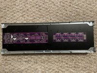
Thanks for an incredibly smooth GB experience and once again for the incredible guides. Just sharing a pic for those considering the 60 in a 4U/500 or similar. Still won't get to the build for some time, but I had to at least take a look.
Note - I'll fix the gap between the sinks. With 6 devices per side on each sink, it shouldn't matter too much, but I like them to be snug against each other. One got a bit banged up in shipping, and it needs a touch of love.
Note - I'll fix the gap between the sinks. With 6 devices per side on each sink, it shouldn't matter too much, but I like them to be snug against each other. One got a bit banged up in shipping, and it needs a touch of love.
Attachments
It would be nice to have the option to try a dual mono supply as an experiment, if a PSU I already have could be easily adapted for it. I'm thinking the F3's supply can be, except it's 200VA per channel rather than what looks like the recommended 300VA per channel (and 5W power resistors, etc) that a dual mono (V8) PCB would seem to ask for. This is possible because the AS-2218 that csample used and I followed can be configured to create a center tap. I'm fine for now with the "new original" F5 PSU board I have, thank you.For mono A30 with the Antek AS-2218 you'll run 1 donut per channel, 1 bridge per secondary pair into a mono (V8) PCB. Easy.
But I think you have a stereo board... Did you want to try mono boards?
I have never heard of a single donut per rail (parallel secondaries into each bridge). Has anyone tried this? Can it work?
Thanks for an incredibly smooth GB experience and once again for the incredible guides. Just sharing a pic for those considering the 60 in a 4U/500 or similar. Still won't get to the build for some time, but I had to at least take a look.
Note - I'll fix the gap between the sinks. With 6 devices per side on each sink, it shouldn't matter too much, but I like them to be snug against each other. One got a bit banged up in shipping, and it needs a touch of love.
@ItsAllInMyHead
Thanks for posting that pic. The more I look at it...the more I realize that a 4U/500 may be what I need to do. The problem with a 4U/400 other than the depth (400mm dimension), is that if you want to mount the boards with one on top and one on bottom, you cannot. The top to bottom distances including the MOSFETS is approximately 120mm for each board. So that's 240 mm which is already too tall for a 165 mm height 4U heatsink.
@rhthatcher
Thanks for the updated drawings!
Best,
Anand.
Hi Anand! Hope all's well. I tried to execute a similar thought to yours with a 5U/400 I have sitting vacant. It was to be the home of my Singing Bush, but I have other plans. The 5U/400 just doesn't quite get it there with any simple config that I could work out. 500 deep is a treat for anything, but rack space.
@ranshdow
What PSU do you have currently? It's likely that dual mono for single rail won't go into dual mono dual rail. w/o another set of boards / parts. tl;dr, easy, but more expensive. I've personally been advised to never parallel transformers prior to rectification. However, that's not "knowledge" that I personally possess, and I can't tell you 'why'. I'm just parroting from a trusted source, ZM, for a different build.
Initial thoughts are:
I'd get a bigger transformer for a single, dual rail PSU,
OR
another set of PSU boards/parts for dual mono if you know you want to experiment. The nice part with that solution, is that if you matched your build for your F3 PSU, you'll have caps rated high enough for some "bigger" dual-rail amps also later. Just swap the transformer. Downside is that all the parts for a new PSU will likely be more than a single / bigger transformer. 6 <=> 1/2 dozen.
Lastly - That schematic has what I'd consider to be a potentially lethal design flaw with the chassis being separated from earth safety ground by the thermistor I'm just a noob with this stuff, and I cast no aspersions. I also don't care to go over and read other comments in another thread. However, I'd strongly recommend that you get confirmation from someone far more experienced than I before emulating that part of the design. I've not reviewed any other aspect. Out of respect for them, I'll '@' them here, so they can respond to my potentially trivial concern. @csample, I mean no disrespect, and if that's been reviewed, my humblest apologies. Just mentioning out of an abundance of concern.
Edited to add - Because (I hope) we're all here to learn. I did not want to delete my concern. I just looked at some (what I consider to be) early schematics of the Aleph designs. Also, the one from CSample above lists Nelson Pass on the schematic. To the point, I've now seen thermistors directly between the chassis and earth GND on a few schematics from credible sources. I thought this was a huge no-no. Clearly I was wrong, and I have more to learn. Sorry!
@ranshdow
What PSU do you have currently? It's likely that dual mono for single rail won't go into dual mono dual rail. w/o another set of boards / parts. tl;dr, easy, but more expensive. I've personally been advised to never parallel transformers prior to rectification. However, that's not "knowledge" that I personally possess, and I can't tell you 'why'. I'm just parroting from a trusted source, ZM, for a different build.
Initial thoughts are:
I'd get a bigger transformer for a single, dual rail PSU,
OR
another set of PSU boards/parts for dual mono if you know you want to experiment. The nice part with that solution, is that if you matched your build for your F3 PSU, you'll have caps rated high enough for some "bigger" dual-rail amps also later. Just swap the transformer. Downside is that all the parts for a new PSU will likely be more than a single / bigger transformer. 6 <=> 1/2 dozen.
Lastly - That schematic has what I'd consider to be a potentially lethal design flaw with the chassis being separated from earth safety ground by the thermistor
I'm just a noob with this stuff, and I cast no aspersions. I also don't care to go over and read other comments in another thread. However, I'd strongly recommend that you get confirmation from someone far more experienced than I before emulating that part of the design. I've not reviewed any other aspect. Out of respect for them, I'll '@' them here, so they can respond to my potentially trivial concern. @csample, I mean no disrespect, and if that's been reviewed, my humblest apologies. Just mentioning out of an abundance of concern.Edited to add - Because (I hope) we're all here to learn. I did not want to delete my concern. I just looked at some (what I consider to be) early schematics of the Aleph designs. Also, the one from CSample above lists Nelson Pass on the schematic. To the point, I've now seen thermistors directly between the chassis and earth GND on a few schematics from credible sources. I thought this was a huge no-no. Clearly I was wrong, and I have more to learn. Sorry!
Last edited:
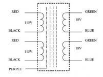
It's the one shown below, but with the crucial difference that each channel has it's own toroid with dual secondaries as shown in the second image of the AS-2218 toroid wiring diagram. Those secondaries are wired in series, e.g. 'dot' to 'no-dot' or "blu" to "gr", to give 36VAC, separately and independently for each toroid. The effective center tap created by wiring in series isn't attached to anything else in the F3 configuration. What I'm hypothesizing is that this unwired center tap can be defined as the new circuit ground, resulting in a PSU giving +/- 24V against that circuit ground. It would then need thermistors, one per channel, between the center tap and earth safety ground, to provide thermistor protection on the secondary side (the primaries already have their own thermistors).@ranshdow
What PSU do you have currently?
There is no paralleling of transformers in this application; all rectification and filtering circuitry on the secondary side is completely separate for each toroid and channel. The PSU caps I used are rated 63V.
The chassis and trafo shield wires in my build are directly wired to earth safety ground with no thermistor between them. Circuit ground, e.g. the 0V side of the PSU outputs, has thermistors between it and earth ground, one thermistor per channel, on the PSU board. I'm saying those thermistors would have to be taken out of circuit if the 0V circuit ground got redefined as -24V, because now there's a huge potential difference between it and earth ground. You can't really tell in this picture but the green wire from the IEC plug attaches to 'ground' on the PSU, and from there another wire goes to star ground, where chassis and trafo shield wires attach.
I feel like I've consumed a lot of oxygen in this thread already so I'd like to leave it at this, but please know I'm always open to direct messages, especially if there is some grevious error in my logic or understanding.
Thank you everyone for your attention.Attachments


Edited to add - Because (I hope) we're all here to learn. I did not want to delete my concern. I just looked at some (what I consider to be) early schematics of the Aleph designs. Also, the one from CSample above lists Nelson Pass on the schematic. To the point, I've now seen thermistors directly between the chassis and earth GND on a few schematics from credible sources. I thought this was a huge no-no. Clearly I was wrong, and I have more to learn. Sorry!
I was going to point that out, but it seems you found that one out looking at the classic schematics. If you want an alternate scheme look at the F5 Turbo article with a bridge and CL60. Or 2 big diodes and a resistor - see some Singing Bush PSU boards. All provide the ground lift / hum break function. You could argue the capability to carry fault current between the solutions. Ideally, the fuse pops before that's an issue.
HI Randy - yep. I may use something similar to the Singing Bush PSU design from Botte that I sent to you. May even do CLC this time or something like the SLB. Still undecided. I really like the boards you sent. The bridge incorporation a la F5T is also easily doable. I've used the thermistors frequently between the signal ground and chassis also in all my FW-based designs. I just had never seen one directly between earth and chassis. Live and learn. Cheers!
No problemEdited to add - Because (I hope) we're all here to learn. I did not want to delete my concern. I just looked at some (what I consider to be) early schematics of the Aleph designs. Also, the one from CSample above lists Nelson Pass on the schematic. To the point, I've now seen thermistors directly between the chassis and earth GND on a few schematics from credible sources. I thought this was a huge no-no. Clearly I was wrong, and I have more to learn. Sorry!
For information purposes one correction is needed, both the FirstWatt F1 original power supply and the clone boards that I made do ground the chassis directly to the incoming safety earth wire through the fasteners that mount the boards. Only the ground feeding the amplifier circuit is lifted by the thermistors.Attachments

@poseidonsvoice check out ItsAllInMyHead build in Pico's 4U500 chassis (post 1177 if the link doesn't work). Dual mono with long amp boards on both heatsinks. I'm trying to get interest in ordering more of these chassis for exactly projects like this. Aleph 60 with dual mono should slide right in.
https://www.diyaudio.com/community/...who-is-interested.360807/page-59#post-6562502
https://www.diyaudio.com/community/...who-is-interested.360807/page-59#post-6562502
Aleph 3 declared as 250W of heat, sum
Aleph 30 declared as 200W of heat, sum
Aleph 60 declared as 220W of heat, sum
4U/400 will cruise all year with 80W per side, 100W with Babysitter
4U/500 say 20W more than 4U/400
5U/500 30 to 35W more than 4U/400
you can change dissipation of amp, if needed
Aleph 30 declared as 200W of heat, sum
Aleph 60 declared as 220W of heat, sum
4U/400 will cruise all year with 80W per side, 100W with Babysitter
4U/500 say 20W more than 4U/400
5U/500 30 to 35W more than 4U/400
you can change dissipation of amp, if needed
^ Or they just run warmer. Po-tae-to, Po-tah-to.
@a007udio - My BA-3 in the 4U/500 dissipates ~120W per side. It's warm, sure. ~34C over ambient with no fans, but nothing over it. This time of year in MN, it's nice. I had it at 0A5 per device (12 devices) on 24V rails for ~144W per side at one point. That was too warm, and (to me) didn't provide any benefit, so I backed down. However, for some FABs, people that have cooler ambient temps, or that use a fan, it might be perfectly fine.
tl;dr - I think I'll be OK with the Aleph 60 and be in no danger of the devices (or my hands) getting too hot, but if not... I'll use bigger sinks or a fan.
@a007udio - My BA-3 in the 4U/500 dissipates ~120W per side. It's warm, sure. ~34C over ambient with no fans, but nothing over it. This time of year in MN, it's nice.
I had it at 0A5 per device (12 devices) on 24V rails for ~144W per side at one point. That was too warm, and (to me) didn't provide any benefit, so I backed down. However, for some FABs, people that have cooler ambient temps, or that use a fan, it might be perfectly fine. tl;dr - I think I'll be OK with the Aleph 60 and be in no danger of the devices (or my hands) getting too hot, but if not... I'll use bigger sinks or a fan.
- Home
- Amplifiers
- Pass Labs
- Classic Aleph Amplifier for Modern UMS Chassis Builder's Thread