Hi all,
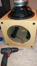
I have this Computer 2.1 woofer. Would like to know how it works. The enclosure is divided in two parts, A and B. B Part (Shown in light blue color) is sealed. Speaker cone faces the A section. This A section has port which passes through B section to the listener. My question are...
1) if one wants to remove the port make a sealed woofer (speaker cone facing listener) which section volume should be considered ?
2) If one wants to make speaker cone and port both front facing how to go about it ?
thanks

Those speakers parameters are suited for ported design1) if one wants to remove the port make a sealed woofer (speaker cone facing listener) which section volume should be considered ?
Phase matching is important, else bass will get cancelled2) If one wants to make speaker cone and port both front facing how to go about it ?
Try some filler material instead
I found John Murphy’s book on speaker design really good, it is inexpensive if you get the kindle version. https://www.trueaudio.com/ild_abt1.htm
The answer is simple. It is necessary to remove the driver, measure the TS parameters, do a simulation for a compression or bass reflex box in one of the many free box simulators and then do it.View attachment 1227596
Hi all,
I have this Computer 2.1 woofer. Would like to know how it works. The enclosure is divided in two parts, A and B. B Part (Shown in light blue color) is sealed. Speaker cone faces the A section. This A section has port which passes through B section to the listener. My question are...
1) if one wants to remove the port make a sealed woofer (speaker cone facing listener) which section volume should be considered ?
2) If one wants to make speaker cone and port both front facing how to go about it ?
thanks
In this case I think it's a waste of time, honestly. The passband box is more efficient than other designs, and nothing is gained by changing the design. If there is no damping in the box, adding it to achieve a cleaner sound is all that can be practically done.
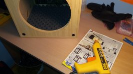
The pictures show the Monitor Audio ASW100. After this it worked audibly better, the box can't be without any damping material.
In the case of bass reflex boxes, only the walls are covered, the compression box is filled entirely with polyester wadding or similar. The electronics, the ports and the driver are never covered. Ports must be free for air flow, electronics due to heating, and the driver due to mechanical movement.
Attachments
Thanks everyone.
So this is 'single vented band pass woofer' design. so enclosure design is specific (Enclosed volume/s works with port for band pass and extension) and altering that would not be good.
Asking Just out of curiosity, what happens if one closes the port and makes same diameter hole on A section. Would that remove low frequency extension provided by port ? Please see pic attached.
Thanks again.
You can't just drill a hole, you have to put a port of the same diameter and length. The diameter and length of the port is obtained as a result of the calculation and is related to the parameters of the driver and the volume of the box.
https://www.ajdesigner.com/speaker/bcb.php
https://www.ajdesigner.com/speaker/bcb.php
You change the tuning frequence of the vented box.Asking Just out of curiosity, what happens if one closes the port and makes same diameter hole on A section. Would that remove low frequency extension provided by port ? Please see pic attached.
From this
you get this (the length of the port is the thickness of the panel)
Last edited:
Dear Nixie62
Can I ask that from you to post a picture of the circuit board ?
Unfortunately a few capacitors on my asw100 subwoofer just "blown up" after given a strange noise.
I would like to replace them but I don't know the volume of them
So it would be a great help to see the resistance color code on the circuit board.
Kind regards
Attachments
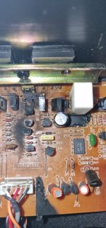
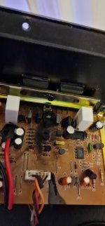
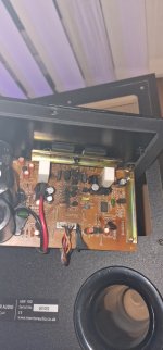
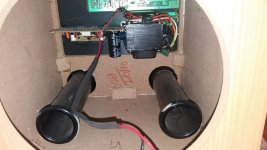
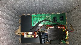
Pictures of the ASW100 refresh and modification:
https://www.diyaudio.rs/topic/10456-monitor-audio-asw100-sub-refresh/#comment-412894
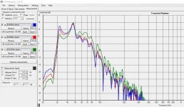
Schematics are in attachment with a measurement. I got them from Monitor Audio on request, a very fair company. They sent me the schematics through the local distributor in Serbia. I don't use SUB, it was for my sister. After modifying a box damping and replacing all electrolytic capacitors, it sounds much better.
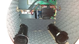
This in the pictures seems to me as if the output transistors (and lot of other things) have gone to the eternal hunting grounds. You will have to desolder and test all the semiconductors, as well as all suspicious passive parts. But first check if the speaker survived.
https://www.diyaudio.rs/topic/10456-monitor-audio-asw100-sub-refresh/#comment-412894
Schematics are in attachment with a measurement. I got them from Monitor Audio on request, a very fair company. They sent me the schematics through the local distributor in Serbia. I don't use SUB, it was for my sister. After modifying a box damping and replacing all electrolytic capacitors, it sounds much better.
This in the pictures seems to me as if the output transistors (and lot of other things) have gone to the eternal hunting grounds. You will have to desolder and test all the semiconductors, as well as all suspicious passive parts. But first check if the speaker survived.
Attachments
Last edited:
There is a lot of work there, good luck. Beware of fake transistors, buy from Mouser, Digi Key and the like. Those output transistors are the most faked.
The speaker (10" bass driver 4ohm) is directly connected to the output, it does not have any protection. I hope it survived, because if it didn't, then it has to be rewound, an then the question arises of the cost-effectiveness of the repair.
The speaker (10" bass driver 4ohm) is directly connected to the output, it does not have any protection. I hope it survived, because if it didn't, then it has to be rewound, an then the question arises of the cost-effectiveness of the repair.
- Home
- Loudspeakers
- Multi-Way
- Computer Ported woofer design question