@swiegert2011 great to have some interest in high SPL speakers.
For some reason I wrote down the wrong number of comps on the Anya, as per the diagram in post #10 its 14 compression drivers.
looking forward to the cardboard J7!
I think EAW use a 15" as the driver is mostly direct radiating and it fits the physical size of module they want. Danley use a 10" as they employ horn loading, they will get more output in the 100Hz+ region from more smaller cones and it fits the physical format of the box better. 105dB/2.83V sensitivity from 120Hz is pretty good! EAW have the luxury of many boxes in a hang, Danley only gets one per side.

I think the best aproach to a single high output speaker is probobly a hybrid of the Danley, EAW, JBL and Fulcrum acoustics aproaches.
There is the LA-WG10 and the LA-WG14 waveguides from Eminence, the LA-WG10 is the 1" throat version.What size is the throat hole on the knock-off waveguide? 1" or 1.4"? B&C says the ME102 is 1" but Eminence says theirs is 1.4"
For some reason I wrote down the wrong number of comps on the Anya, as per the diagram in post #10 its 14 compression drivers.
looking forward to the cardboard J7!
I think EAW use a 15" as the driver is mostly direct radiating and it fits the physical size of module they want. Danley use a 10" as they employ horn loading, they will get more output in the 100Hz+ region from more smaller cones and it fits the physical format of the box better. 105dB/2.83V sensitivity from 120Hz is pretty good! EAW have the luxury of many boxes in a hang, Danley only gets one per side.
I think the best aproach to a single high output speaker is probobly a hybrid of the Danley, EAW, JBL and Fulcrum acoustics aproaches.
Basic unbaffled 4 element array simulation to show the idea working. Vertical polar information:
Some interesting behaviour, narrower than expected below 3k, combing evident at high frequencies. Something weird at 5k. Beam width is basicly 60 degree as desired in the 3k -20k range this would be operating though. May improve with a horn?
Are you able to test the response of a "real" ME102 vs cheap one? I wonder if they test the same.
A 1 inch CD typically fills a normal horn more evenly than a 1.4" or 2". I would assume adding a 90° horn flare would positively effect the beamwidth, but not sure what'll happen to the response.
A 1 inch CD typically fills a normal horn more evenly than a 1.4" or 2". I would assume adding a 90° horn flare would positively effect the beamwidth, but not sure what'll happen to the response.
I don't own a real ME102 and their availability is very poor so its not likely unless the aliexpress version has some kind of issue as interesting as that would be.
I have used ATH+ABEC to design a R-OSSE flare to use on the horizontal. Diameter is 12cm, target 90 degree dispersion. I wanted to minimise this to avoid too much shadowing of the midrange horn so dispersion is a bit broad at 3k; 106 degree but I think this is a good comprimise on keeping the waveguide small to avoid blocking too much of the midrange horn. Target dispersion achived to 13.25k dropping to 60 degree by 17.65k caused by throat diameter.


I have used ATH+ABEC to design a R-OSSE flare to use on the horizontal. Diameter is 12cm, target 90 degree dispersion. I wanted to minimise this to avoid too much shadowing of the midrange horn so dispersion is a bit broad at 3k; 106 degree but I think this is a good comprimise on keeping the waveguide small to avoid blocking too much of the midrange horn. Target dispersion achived to 13.25k dropping to 60 degree by 17.65k caused by throat diameter.
Attachments
Interesting results from a free standing non circular symetric version for a single line array element; the horizontal pattern is much broader at 3k, pattern control seems to be at a higher frequency than the freestanding circular symetric case. Perhaps as I added a rear side roundover?
Back:

front:


Back:
front:
@kipman725 have you considered a longer expanding horn? I wonder if the pattern doesn't have time to develop with such a short waveguide. Looking at other line array waveguides, some are direct angles like that, but others flare out. Reading up on tractix horns, it would seem that flaring out to any degree would yield a better result than just a flat wall right away. If it's all air pressure at the end of the day, a straight 90° nozzle on a hose wouldn't blast that pressure equally all directions. It would need some guidance first.
If you start at the driver with straight walls, then expand to 5.63°, then 11.25°, then 22.5°, then 45° on either side so that you get to 90° total. It's easy to map out if you have some graph paper. Then transfer that to a solid, flat surface and glue the pieces in place for one side of your horizontal walls. If the pieces are tall enough, you can measure out the vertical angle and cut that wall in half according to the vertical angle to get your two horizontal sides with the correct vertical. Hoping the geometry in my head makes sense as I type it out.
If you start at the driver with straight walls, then expand to 5.63°, then 11.25°, then 22.5°, then 45° on either side so that you get to 90° total. It's easy to map out if you have some graph paper. Then transfer that to a solid, flat surface and glue the pieces in place for one side of your horizontal walls. If the pieces are tall enough, you can measure out the vertical angle and cut that wall in half according to the vertical angle to get your two horizontal sides with the correct vertical. Hoping the geometry in my head makes sense as I type it out.
I think I arrived at almost imediate going to 90 degree opening angle as I was getting more HF beaming otherwise but I will look into it again.
I also found this image while looking up line array waveguides which looks suspiciously like the guides I have, clearly from a patent but which one?

I also found this image while looking up line array waveguides which looks suspiciously like the guides I have, clearly from a patent but which one?
A line array "horn" has those pins in it to delay the wavefront so that it's hitting the top and bottom and center of the horn exit at the same time, right? So we can end up with a very wide dispersion with a low vertical dispersion. However, a single horn does not magically make that a cylindrical wavefront. Until it couples with several other waveguides, the whole cylindrical part doesn't really happen and it doesn't happen until it gets further out from the box. So really what we have here when we measure a single horn is just an elongated rectangle exiting the horn. My thoughts is that if we treat it like that, it's still a short horn that hasn't had the time to develop into a guided wavefront, so we need something to make that happen. A waveguide. So a straight 90° angle wouldn't truly be guiding anything in my mind. Perhaps several of the stacked horns and waveguides would better follow a straight 90° path, but one on it's own would not.
We know from studying frequency response with other types of horns that direct angles don't often yield the best results. So I'm not sure that this would be any different.
We know from studying frequency response with other types of horns that direct angles don't often yield the best results. So I'm not sure that this would be any different.
https://patents.google.com/patent/EP1927978B1... clearly from a patent but which one?
Current Assignee: B&C Speakers SpA
Last edited:
@TBTL I guess that clears up who is the orginal designer!
@swiegert2011 I'm trying to simulate just the horizontal flare at the moment hence the isolated units post #23 has a basic array simulation. Good point about the sudden change in wall angle though. I don't have a 3D model of the line array waveguides but if I did I would include it in these simulations.
I had a go at making a deeper waveguide and I think in the process have cleared up what is causing the deviation from the axisymetric case with the widening pattern.
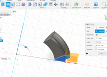
Firstly we have our new deeper horn:


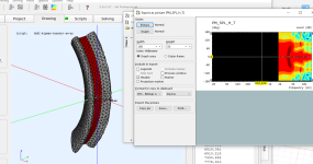
hmm looking very resonant! and nothing like the axisymetric case. Ok lets delete the top and bottom surfaces (15 degree coverage conical horn flare):


not sure whats going on with the contour projection but this is a lot nicer! ok so even with no top and bottom there will be diffraction and acoustic impedance mismatch due to the open top so I will experiment with absorbing top and bottom surfaces.
@swiegert2011 I'm trying to simulate just the horizontal flare at the moment hence the isolated units post #23 has a basic array simulation. Good point about the sudden change in wall angle though. I don't have a 3D model of the line array waveguides but if I did I would include it in these simulations.
I had a go at making a deeper waveguide and I think in the process have cleared up what is causing the deviation from the axisymetric case with the widening pattern.
Firstly we have our new deeper horn:
hmm looking very resonant! and nothing like the axisymetric case. Ok lets delete the top and bottom surfaces (15 degree coverage conical horn flare):
not sure whats going on with the contour projection but this is a lot nicer! ok so even with no top and bottom there will be diffraction and acoustic impedance mismatch due to the open top so I will experiment with absorbing top and bottom surfaces.
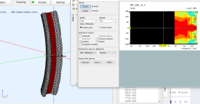
Added blocks of absorbing boundry and the results clean up further:


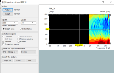
original axisymetric simulation (I think theres a lot of files about...):

I lowered the opening angle to 40 degree for this, I think if I bump it back up to 45 I could get something acceptable.
original axisymetric simulation (I think theres a lot of files about...):
I lowered the opening angle to 40 degree for this, I think if I bump it back up to 45 I could get something acceptable.
Hi, its for line array right? what if you simulate full height system without the top and bottom? I suspect when the line / "stack" is multiple times longer than the width it would simulate nice.
If you need the top and bottom, round them over, its the sharp edge that makes diffraction.
If you need the top and bottom, round them over, its the sharp edge that makes diffraction.
@tmuikku its not a line array the tweeters are arrayed in an arc to simulate a point source but as 4 tweeters rather than 1 are used the output is (hopefully) around 12dB more. At the scale of events we do sometimes a single comp isn't going to cut it. Also the comps cross @3-4k in order to increase effective power handling and I'm going to use ring radiators for HF efficiency. The speaker that this is part of will have fly hardware so no one is going to be very close to it when its running near maximum output.
But is it one module and you will have 4 of these in the speaker? You could simulate the whole thing in ABEC, as four modules I think. You get the wall contour with ATH as axisymmetric device, then import it to some CAD program and extrude the walls? Instead of extruding you can use a revolve or path tool along a path to kind of make quarter of full 4 element system? Or perhaps I'm not following what the process / progress is at the moment 
edit. Here is image what I try to convey, quarter of the complete four tweeter array. Try to get the HF to combine for the output you need.

Although, most of it depends on the initial horns.. perhaps this is not helpful after all
Philosophical thought for your project, as everything is compromise and your main motivation here seems to be to increase output on HF I would accept some diffraction as a compromise. I would do what ever necessary to find out if such high output is possible and then look for ways to reduce diffraction.
Its interesting engineering task, very different from home hifi so I wish you good luck with it! Will follow how it turns out
edit. Here is image what I try to convey, quarter of the complete four tweeter array. Try to get the HF to combine for the output you need.

Although, most of it depends on the initial horns.. perhaps this is not helpful after all
Philosophical thought for your project, as everything is compromise and your main motivation here seems to be to increase output on HF I would accept some diffraction as a compromise. I would do what ever necessary to find out if such high output is possible and then look for ways to reduce diffraction.
Its interesting engineering task, very different from home hifi so I wish you good luck with it! Will follow how it turns out
Last edited:
Tried few quickies from the random profile above just to test if the suggestion works. It is very small model, probably less than half what you have. The top octave is the tough nut and I suggest try to simulate in ABEC as complete system, its pretty fast to tune if you model it like so. Although as speculated above not sure what the response from the initial horn is I'm not sure how much value here is simulating, perhaps its enough what you are doing now to evaluate nice extension profile.


Vertical for the latter

Not sure what is achievable, but I suspect its very hard to get the top to sum constructively, if not impossible? Perhaps you have the realities sorted out already
This was only quick look on it so I could be completely wrong with this but the sim kind of shows the vertical is dictated by the array length and the top and bottom lip aren't very important, at least at this stage of affairs. I think you can add and optimize them later if you want to. I think main problems of such array are on how to combine all the the tweeters, the curvature of the set and how the initial sections work that bring them all together. I'm almost sure any additional structure to the initial horn sections moves existing problems lower in frequency. You should perhaps measure the real thing before going any further with this with the extra horn section to see how they work out alone, in the vertical axis. Perhaps there is opportunity to design custom initial section as well, if the ready made horns won't deliver what you expect them to.


Vertical for the latter

Not sure what is achievable, but I suspect its very hard to get the top to sum constructively, if not impossible? Perhaps you have the realities sorted out already
This was only quick look on it so I could be completely wrong with this but the sim kind of shows the vertical is dictated by the array length and the top and bottom lip aren't very important, at least at this stage of affairs. I think you can add and optimize them later if you want to. I think main problems of such array are on how to combine all the the tweeters, the curvature of the set and how the initial sections work that bring them all together. I'm almost sure any additional structure to the initial horn sections moves existing problems lower in frequency. You should perhaps measure the real thing before going any further with this with the extra horn section to see how they work out alone, in the vertical axis. Perhaps there is opportunity to design custom initial section as well, if the ready made horns won't deliver what you expect them to.
Last edited:
@tmuikku I actualy got pretty reasonable vertical window from correctly arraying sources here: https://www.diyaudio.com/community/threads/constant-curvature-tweeter-array.388439/post-7290771 I'm assuming the planar wave guides are doing their jobs and generate planar waves from an appature the size of their front opening. Your curved version is basicly what I am going to make but it has to be stepped due to the constraints of the planar waveguides, if I was to make my own it could be a continous curve and JBL infact do this for one of their products: https://jblpro.com/en/product_families/vrx-series-constant-curvature-line-array
Looking at your model it looks very low res which might be why you are having issues at higher frequencies. Also what is your source size? this will narrow the high frequencies if its acousticly large. I have attached my 3D model of the ME102/clone if you want accurate dimensions of the planar waveguides. (made from a mix of caliper measurments and the B&C datasheet). I have also attached some MATLAB/OCTAVE for calculating the array element positions and apparent acoustic center.
The reason I previously had 'lips' on my waveguides is that I thought it would be beneficial for combing in the vertical which the unbaffled array was subject to as the line array waveguides do not have constant directivity for the vertical.
Attachments
- Home
- Live Sound
- PA Systems
- Constant curvature tweeter array
