Your right relder. Cu to Al connections in house wiring is a big NoNo because of corrosion and resultant high resistance. I know of one high power TV transmitter maker that tried the Cu/Al heatsink idea. It didn't work, Too expensive, unreliable (due to the bonding method they were using) very small gain in performance. They said that the bonding could have been fixed but the advantages didn't justify the added expence of the copper, let alone the problems.
Give it a shot if you want. I just thought you would like to know.
Later Bruce
Give it a shot if you want. I just thought you would like to know.
Later Bruce
All in all, i feel a Cu "heat spreading" strip is a good idea. I've seen a lot of amps using an Al extrusion/sheet to conect one or more devices to heatsinks, and cooper would perform much better in that kind of situations. It's more expensive/heavier/difficult to work with through.
In the scenario I described, there is no direct cu/al interface. Please read it again. The mica insulator is eliminated from its traditional spot between the device and the al heat sink, and placed between the cu plate and the al heat sink.
Look at Circlotron's link
http://diyaudio.com/forums/showthread.php?s=&threadid=3891&perpage=15&pagenumber=2
Again, this:
1.)makes for a much more intimate interface between the device and the cu plate removing the heat from the device much faster.
2.)moves the high thermal resistance interface to the interface between the cu plate - mica insulator - al heat sink where the increased area of the larger cu plate helps to reduce this thermal resistance.
Again, The important point is that the heat is taken away from the device much faster.
Rodd Yamas***a
The copper heatspreader idea is nothing new. To my knowledge, all new Pentium 4, and Athlopn XP chips REQUIRE a copper heat spreader plate between the chip and the (aluminum) heatsink. A visit to Tom's Hardware Guide will show what happens when it isn't used... talk about an expensive video! hehe.
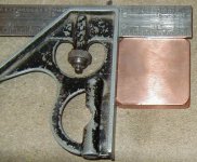
The Geek Group has some 2"x2"x.38" thick copper plates we had intended to sell as spreader plates for overclockers. The plates have been stropped (polished) on both sides and are probably flatter and smoother than your heatsinks and output devices! Unfortunately, the person with the contacts and such left our organization, and left the several hundred plates in our shop. I'd be happy to discuss this more offlist with interested parties.
Mark Broker
mbroker@thegeekgroup.org
Chief Engineer
Attachments
Roddyama, How big is this copper heat spreader? The larger in surface area you make the copper the more capitance to ground you will have via the heat sink. I under stand very well what you are talking about. A bypass cap from collector to ground might be OK with you. I just don't think I want one there.
Later Bruce
Later Bruce
relder said:I know aircraft people are always watching out for dissimilar metal interfaces due to eventual structual weakening due to corrosion. Over time corrosion will occur between some dissimilar metals fastened to each other. Hopefully none of us has to worry about structural failure of our ampsbut that corrosion may cause more thermal resistance over time. Not sure if Al and Cu are on that list, but something to perhaps consider.
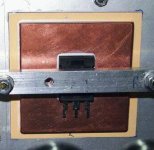
As you can see on inclosed picture there is an insulator sheet between aluminum heatsink and copper spreader, so there is no worry about corrosion.
There is no insulator between device and spreader so capacitance shouldn't be a problem either since both pieces have the same potential.
I only hope that Circlotron won't mind I'm using his pix.
Attachments
Heatsink stuff
Rodd,
Don't agree to your 1). You can consider these thermal resistances as a string of series resistance from the *thermal voltage source* source (the device generating heat) to *thermal ground* (the ambient air). Moving one of the *resistors* physically away from the source doesn't change the thermal current. Like if you would move the load resistance on a voltage source 6 inch away wouldn't change the load current, would it?
2) Yes, effectively you put a lot of *resistors* in parallel which reduces the total and increases the *current*. But again, I wouldnt want to bet any money that it is better than an all-Al heatsink.
Cheers, Jan Didden
roddyama said:In the scenario I described, there is no direct cu/al interface. Please read it again. The mica insulator is eliminated from its traditional spot between the device and the al heat sink, and placed between the cu plate and the al heat sink.
Look at Circlotron's link
http://diyaudio.com/forums/showthread.php?s=&threadid=3891&perpage=15&pagenumber=2
Again, this:
1.)makes for a much more intimate interface between the device and the cu plate removing the heat from the device much faster.
2.)moves the high thermal resistance interface to the interface between the cu plate - mica insulator - al heat sink where the increased area of the larger cu plate helps to reduce this thermal resistance.
Again, The important point is that the heat is taken away from the device much faster.
Rodd Yamas***a
Rodd,
Don't agree to your 1). You can consider these thermal resistances as a string of series resistance from the *thermal voltage source* source (the device generating heat) to *thermal ground* (the ambient air). Moving one of the *resistors* physically away from the source doesn't change the thermal current. Like if you would move the load resistance on a voltage source 6 inch away wouldn't change the load current, would it?
2) Yes, effectively you put a lot of *resistors* in parallel which reduces the total and increases the *current*. But again, I wouldnt want to bet any money that it is better than an all-Al heatsink.
Cheers, Jan Didden
I'm sure that copper is optimal if you take the heat away by a heat pipe.
Maybe copper is better for CPU's because you don't have too much space to mount a heatsink.
In all other cases i'll prefer an aluminum heat sink with a maximum thick back to dissipate the heat.
In amplifiers you can add an extra output device which usually improves heat dissipation amongst other benefits.
The way I see it is you ultimately have to have an insulator somewhere between the live tab of the fet and the earthed heatsink. The insulator I used from memory has a thermal resistance of 0.2 deg C per watt per square inch. At about 1/2 a square inch for the back of a TO-247max package that's 0.4 deg C drop for every watt you put through it. But if we bung the fet straight on the copper with a bit of paste, and put the insulator between the copper and the aluminium, it now has 4 square inches of area so the Rth is 0.05 deg C per watt. Improved by a factor of 8. The fet to copper junction is not perfect but way better than it would have been.
As a matter of fact the capacitance increases by a factor of 8 too. But with this circlotron topology the whole filter cap bank to earth and the transformer secondary windings to earth are jiggled up and down at audio frequency too so this capacitance to the heatsink is only a drop in the ocean...
GP.
Copper for a heat sink???
Yes it is true that copper is a better conductor of heat & electricity than aluminum, but there is one fundamental problem with copper. It is corrosive. After the copper heat sink turns green from copper sulfide, it won't conduct heat to the air anymore.
Yes it is more dense and would be smaller in size than a aluminum one but aluminum doesn't corrode. However you could plate the coper heat sink with gold and it would be perfect.
How much money do you have???????

Hi... this old thread still remains a good talk...
Well, I saw you took care about electrolytic corrosion between Cu and Al at heatsink interface - in some cases we can consider that following:
the small TAB on the FET is made of what? As majority of parts it should be Tinned Cu, I think electrolytic corrosion can be avoided with some thin (...) layer of Sn/Pb or maybe only Sn over the Cu plate and get thermal resistance even lower at the interface, as tin is much better heat conductor than mica or any other sintetic polymer where isolation was a real need. If the FET tab is the "live" connection, we should not do this but if the part has tab connected to ground, I think it is a good solution, IMO.
Hisatugo
- Status
- This old topic is closed. If you want to reopen this topic, contact a moderator using the "Report Post" button.
- Home
- Amplifiers
- Solid State
- Copper/Aluminum heatsink - yay or nay?