Hello, I don't know if I can get a reply.
I paid attention to the maintenance of all officials in Counterpoint-SA. One of the impressive is the maintenance of Pars 12 years ago, in which Vivavee, who participated, knows Counterpoint-SA220 very well.
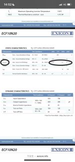
My current maintenance status is: I bought 10 pairs of paired yellow ribbons before exicon stopped production to3 10n20 10p20 (at that time, the yellow ribbon was the best). Of course, this 220 needs 8 pairs, but this also means that I can't make any mistakes. At present, I have changed it to pcb to reverse the D and S of mosfet, and also changed the original 10v protection secondary tube to 6.8v horizontal mosfet gat is +-14v to reverse the DS protection secondary tube because D and S are the opposite.
Q1 has burned my location. Only 2n2222A is to18 package. No 2n2222 is to92. They seem to have a difference of 250ft and 300ft, so I changed it to 2n2222A.
The 1n5303 has also been burned, and the 60v diode is not damaged. Oh, if you can't buy 1n5303, I will change it to 1.6ma, which is close to 1n5303.
At present, my question is
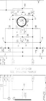
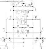
There are many different parts specifications and circuit diagrams of this machine, such as r5 r8. The picture is 51r. The machine is located at 681r. I want to change it back to 51r, but the vr1 picture is 100k. The original installation is 250k and has been burned. Should I choose 100k in the picture? Or the original 250k? It should still be changed to a larger 500k horizontal mosfet.
The bias seems to be smaller. ( The yellow bag is 135ma-150ma)
Exicon mosfet gat is max1.5v, but I found two sets of vr, vr1 and vr2 in the circuit diagram. Vr1 seems to write off set for adjusting the article to the current. I don't know much about its use...
This machine is the first power amplifier I repaired is for my own use, and I have never seen this machine work normally. Before I bought it, these machines were abandoned for maintenance for more than 10 years, and there are many uncertainties.
By the way, I have spent $1,000 on repairing and replacing, cleaning up dusty boards to replace broken wires, a pile of previously burned or wrong resistors and aging electrolytic capacitors. I upgraded its specifications to 220uf 400v, and the copper foil is very fragile to make up for countless lines.
... Now the price is close to about $1,500 to buy a working device directly. But this is the first power amplifier I repaired, and I still hope it can be repaired smoothly.
I hope someone can reply to me. Thank you very much!
I paid attention to the maintenance of all officials in Counterpoint-SA. One of the impressive is the maintenance of Pars 12 years ago, in which Vivavee, who participated, knows Counterpoint-SA220 very well.
My current maintenance status is: I bought 10 pairs of paired yellow ribbons before exicon stopped production to3 10n20 10p20 (at that time, the yellow ribbon was the best). Of course, this 220 needs 8 pairs, but this also means that I can't make any mistakes. At present, I have changed it to pcb to reverse the D and S of mosfet, and also changed the original 10v protection secondary tube to 6.8v horizontal mosfet gat is +-14v to reverse the DS protection secondary tube because D and S are the opposite.
Q1 has burned my location. Only 2n2222A is to18 package. No 2n2222 is to92. They seem to have a difference of 250ft and 300ft, so I changed it to 2n2222A.
The 1n5303 has also been burned, and the 60v diode is not damaged. Oh, if you can't buy 1n5303, I will change it to 1.6ma, which is close to 1n5303.
At present, my question is
There are many different parts specifications and circuit diagrams of this machine, such as r5 r8. The picture is 51r. The machine is located at 681r. I want to change it back to 51r, but the vr1 picture is 100k. The original installation is 250k and has been burned. Should I choose 100k in the picture? Or the original 250k? It should still be changed to a larger 500k horizontal mosfet.
The bias seems to be smaller. ( The yellow bag is 135ma-150ma)
Exicon mosfet gat is max1.5v, but I found two sets of vr, vr1 and vr2 in the circuit diagram. Vr1 seems to write off set for adjusting the article to the current. I don't know much about its use...
This machine is the first power amplifier I repaired is for my own use, and I have never seen this machine work normally. Before I bought it, these machines were abandoned for maintenance for more than 10 years, and there are many uncertainties.
By the way, I have spent $1,000 on repairing and replacing, cleaning up dusty boards to replace broken wires, a pile of previously burned or wrong resistors and aging electrolytic capacitors. I upgraded its specifications to 220uf 400v, and the copper foil is very fragile to make up for countless lines.
... Now the price is close to about $1,500 to buy a working device directly. But this is the first power amplifier I repaired, and I still hope it can be repaired smoothly.
I hope someone can reply to me. Thank you very much!
Attachments
-
 DA7A355E-A634-4D00-A4DD-38CADA341736.png725.5 KB · Views: 344
 -
 1CED17C4-A2D8-43FE-A81E-9DA25819DABF.jpeg147.5 KB · Views: 334
 -
 24F29180-C3A2-47F7-ABE0-4E23BA499749.jpeg119.3 KB · Views: 272
 -
 5AC4BEA4-DA8D-4FDE-83EA-2998FC44A42D.jpeg158.7 KB · Views: 252
 -
 49FDB5B3-914B-463E-90C1-2947F9730B83.jpeg390.3 KB · Views: 316
Last edited:
Hello, I saw the change method of the critical repair circuit of the sa100. Is it still okay if it needs to be run on the sa220? And I still haven't confirmed the vr1 specification. I hope someone can help me. Thank you very much.
The original part was a side adjust part - which was just plain stupid because that made it difficult to get at the adjust screw.
So use this top adjust Bourns 25T cermet trimmer - 3296W-1-104LF

So use this top adjust Bourns 25T cermet trimmer - 3296W-1-104LF


I think VivaVee would agree with me on this. The only real fix is a new designed output stage. The original design is flawed in so many ways! He's got a new one designed I think, and I will be returning to design a new output stage. Corrections in the power supplies and voltage amps stages as well.
Because there are no source resistors, you need to match the new outputs very tightly, and I mean very tightly.
-Chris
Because there are no source resistors, you need to match the new outputs very tightly, and I mean very tightly.
-Chris
Hi Chris,
Yes, and source resistance kills the sound quality (or Counterpoint would have used them).
I am designing new output stages again. I stopped for a while as the guy I was working with ripped me off. He took off with something that sort of worked. Joke is on him.
These amplifiers need some design changes in every area. However, even the intrum designs blew the original away for sound quality while retaining the Counterpoint signature sound. Distortion was greatly reduced and they were very reliable, running at much lower bias currents too. That reduced transformer core temperature. A few failure points were completely eliminated.
So I will begin and pick up where I left off years ago. The number of hacked amps and preamps just keeps going up and I am getting more to rebuild. Once redesigned, the preamps sound better and run problem free for years now, no failures yet.
So yes, well worth a design. People who liked SA-100's love the redesigned models even at the stage they are at now. Once the SA-100 is done, the design will be engineered for the SA-220 voltage levels.
-Chris
The essential problem with the SA12/20/100/220 is that the output MOSFETs had no source resistors. The only reason that every amp did not self destruct due to thermal runaway in minutes was due (despite the internet morons who think otherwise) to the heroic matching of the dual/quad set of N/P channel MOSFETs at a high quiescent current. In my experience, this effort meant that the amps mostly worked OK but did not achieve acceptable long term reliability.
Possible solutions
1. Lower the quiescent current dramatically (and ignore the distortion from the Class B operation)
2. Add source resistors (and ignore the significant rise in output impedance)
3. Understand how VMOS switches work and bias the output stage above the positive/negative temp coefficient inflection point, which means a higher Iq and a dramatically bigger heatsink and transformer than is in the box at the moment.
3. Accept that these original devices were intended for use as industrial switches rather than linear operation, and replace the output stage with one based on BJTs.
4. Gut the nice box and put a reliable amp design inside it...
Hi VivaVee,
Lol!
Yes, pretty much. You are exactly right on all counts.
Option 3 with voltage amp and power supply redesign is the best option. You do have a new BJT output design as I recall.
Stick another design in? Well, it is not longer a Counterpoint then and is simply a box now. May as well replace the faceplate with something reflecting the new design.
The first time I saw someone gut an Audio Research SP6 and put their own design in, I screamed sacrilege!
However, at a certain point the only real value an old amp has is the case, PSU and connectors - and that amounts to a significant percentage of the cost of an amp, so a really really good start.
And if you redesign the bejesus out of the original design, as you intend, I would suggest it is no longer a Counterpoint either. Just saying...")
However, at a certain point the only real value an old amp has is the case, PSU and connectors - and that amounts to a significant percentage of the cost of an amp, so a really really good start.
And if you redesign the bejesus out of the original design, as you intend, I would suggest it is no longer a Counterpoint either. Just saying...
I would agree, but I keep the same basic design and it still sounds like a Counterpoint. If the sound character changed, you are absolutely correct.
The one thing that is totally different is the output stage, same as for you. Otherwise, the basic signal path is how it was originally designed with a couple changes that greatly reduce distortion. If it sounded different, I would call it a different design, the only real change is distortion (much lower). It was actually harder to retain the sonic character of the original than to make it better across the board. People wanted the Counterpoint sound. They are thrilled with the lower distortion.
The one thing that is totally different is the output stage, same as for you. Otherwise, the basic signal path is how it was originally designed with a couple changes that greatly reduce distortion. If it sounded different, I would call it a different design, the only real change is distortion (much lower). It was actually harder to retain the sonic character of the original than to make it better across the board. People wanted the Counterpoint sound. They are thrilled with the lower distortion.
Hello, Vivavee
Well, I'm going to use 100k vr for this vr at present. It seems to be a 25-rpm Bourns.
I realized that I had to redesign the bias to the voltage. The original circuit will get a deviation of 3.8-4v, while the exicon needs about 1v below 1.5v.
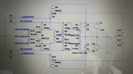
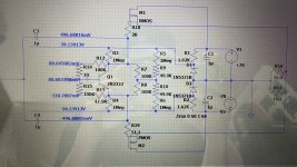
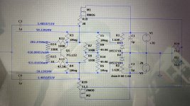
I tried to build a circuit in LTspice to get a voltage of less than 1.5v. The data I obtained is as follows.
I removed R17 because it will increase the circuit by 1.2v. I guess it is the vbe that protects 2n2222. The maximum voltage of only 1.5v here should not be needed
Through several simulations, I have changed R15 to 100k vr so far, which is also 100K. The voltage can show an adjustment range of 0.5v-1.5v in the simulation.
Should I do this? Thank you very much.
Well, I'm going to use 100k vr for this vr at present. It seems to be a 25-rpm Bourns.
I realized that I had to redesign the bias to the voltage. The original circuit will get a deviation of 3.8-4v, while the exicon needs about 1v below 1.5v.
I tried to build a circuit in LTspice to get a voltage of less than 1.5v. The data I obtained is as follows.
I removed R17 because it will increase the circuit by 1.2v. I guess it is the vbe that protects 2n2222. The maximum voltage of only 1.5v here should not be needed
Through several simulations, I have changed R15 to 100k vr so far, which is also 100K. The voltage can show an adjustment range of 0.5v-1.5v in the simulation.
Should I do this? Thank you very much.
Attachments
Hello Anatech, I saw that the sa100 modification board you designed includes two versions of exicon mosfet and BJT.
Among them, you removed 2n2222 in the mosfet version. Well, I know that exicon officially said that the complete negative temperature coefficient can even operate without protection, but I don't think so...
Well, I still don't want to increase the source resistance. I want to listen to the original counterpoint sound.
Thank you for your reply
Well, it seems that this is the only choice in front of me: 3. Understand how VMOS switches work and bias the output stage above the positive/negative temp coeffic Ient inflection point, which means a higher Iq and a dramatically bigger heatsink and transformer th An is in the box at the moment.The essential problem with the SA12/20/100/220 is that the output MOSFETs had no source resistors. The only reason that every amp did not self destruct due to thermal runaway in minutes was due (despite the internet morons who think otherwise) to the heroic matching of the dual/quad set of N/P channel MOSFETs at a high quiescent current. In my experience, this effort meant that the amps mostly worked OK but did not achieve acceptable long term reliability.
Possible solutions
1. Lower the quiescent current dramatically (and ignore the distortion from the Class B operation)
2. Add source resistors (and ignore the significant rise in output impedance)
3. Understand how VMOS switches work and bias the output stage above the positive/negative temp coefficient inflection point, which means a higher Iq and a dramatically bigger heatsink and transformer than is in the box at the moment.
3. Accept that these original devices were intended for use as industrial switches rather than linear operation, and replace the output stage with one based on BJTs.
4. Gut the nice box and put a reliable amp design inside it...
My current exicon is a pairing version of the forbidden current, which should be between 135-150ma according to the official specifications, so I may have to adjust vr1 to get 540mA current after confirming the modification?
Well, this seems stupid, but I want to try passive resistance. At present, I can confirm that I can make the machine operate at an ambient temperature of about 16 degrees or increase the heat dissipation fan if the radiator is overheated.
Before that, I must confirm whether it is feasible to modify the output level voltage bias?
Thank you very much
Hi William,
You have mistaken me for someone else. I have never designed with new mosfets for this amplifier, nor would I publish the design if I did.
I have designed a bipolar replacement that does retain the sound quality and character of the original. The actual sound quality is massively improved in fact. Once I am done, the design will be implemented by me only. I have seen incredible hack work out there, and will not have my name associated with that kind of work. Some of my designs have been copied and attributed to me (they aren't accurate copies and don't work as well). You have no idea what it feels like to have someone bring you a disaster telling you it is your design and can you fix it. What they bring you is not what you designed, and it sure isn't how you work. That's what it does to your name and reputation. Imagine how many never talk to you and assume it is your work and you are incompetent?
The corrections involve rewiring, new boards and neat workmanship is required to pull it off well. Just like in any amplifier design. From what I am seeing out there, some DIY members could easily do it properly. Many won't / can't. Then there are all the lurkers and others who just rip off designs. Too much design time and experience goes into things like this to have it poorly executed by others for profit without due care for the equipment owner.
- Home
- Amplifiers
- Solid State
- Counterpoint-SA220-pwr to Exicon mosfet 10N20 10P20 TO3