Hi there !
After an attempt to design a bluetooth DAC, with questionable technical choices, I decided to be reasonable and make an S/PDIF version.
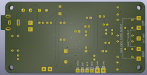
The DAC is still based on the PCM5102A chip, without additional preamplification stage, and the 100x50mm 4-layer PCB receives one ground plane per layer, connected together by vias.
I will use this module for S/PDIF to I2S conversion: https://www.audiophonics.fr/en/inte...spdif-to-i2s-dir9001-24bit-96khz-p-17274.html
For volume control, I'll use this: https://www.audiophonics.fr/en/preamplifier-modules/motorized-volume-control-board-50k-p-15006.html
From what I understand, the DIR9001 module will synchronize to the S/PDIF clock, and the PCM5102A will also synchronize via the I2S bus. I still connected the MCK pin of the DIR9001 module to an oscillator, so the DAC should keep running correctly without an S/PDIF signal, because my Tripath amp does not like to operate without a source.
I placed an LC filter at the 12V input because the DAC will be powered by an external SMPS power supply. Please tell me if the values of this filter are correct.
As advised for my previous design, the low noise 3.3V LDO is cascaded to a much larger 5V LDO to lighten its workload.
As this design was quite conventional, I couldn't resist adding a quirk, a high pass RC filter, for optional use.
Indeed, I chose the PCM5102A because it is the only decent DAC chip that I felt capable of implementing, being a beginner. But I know that it tends to be a little too generous in low frequencies.
So I added this high pass RC filter which cuts at 48Hz in the hope of being able to obtain more controlled and clean bass, if the need arises. I can use capacitors with significantly different values to fine-tune the filter. Let me know if this is a bad idea
EDIT : I just saw a big error on my high pass filter which in reality is a low pass . I am going to correct this and I am thinking of using a relay in order to be able to bypass this filter easily.
And here are the pictures :
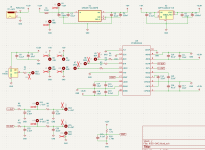
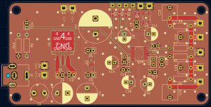
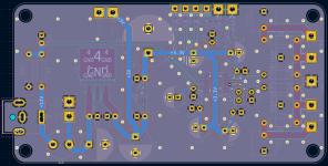
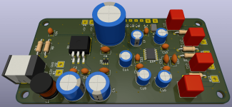
After an attempt to design a bluetooth DAC, with questionable technical choices, I decided to be reasonable and make an S/PDIF version.
The DAC is still based on the PCM5102A chip, without additional preamplification stage, and the 100x50mm 4-layer PCB receives one ground plane per layer, connected together by vias.
I will use this module for S/PDIF to I2S conversion: https://www.audiophonics.fr/en/inte...spdif-to-i2s-dir9001-24bit-96khz-p-17274.html
For volume control, I'll use this: https://www.audiophonics.fr/en/preamplifier-modules/motorized-volume-control-board-50k-p-15006.html
From what I understand, the DIR9001 module will synchronize to the S/PDIF clock, and the PCM5102A will also synchronize via the I2S bus. I still connected the MCK pin of the DIR9001 module to an oscillator, so the DAC should keep running correctly without an S/PDIF signal, because my Tripath amp does not like to operate without a source.
I placed an LC filter at the 12V input because the DAC will be powered by an external SMPS power supply. Please tell me if the values of this filter are correct.
As advised for my previous design, the low noise 3.3V LDO is cascaded to a much larger 5V LDO to lighten its workload.
As this design was quite conventional, I couldn't resist adding a quirk, a high pass RC filter, for optional use.
Indeed, I chose the PCM5102A because it is the only decent DAC chip that I felt capable of implementing, being a beginner. But I know that it tends to be a little too generous in low frequencies.
So I added this high pass RC filter which cuts at 48Hz in the hope of being able to obtain more controlled and clean bass, if the need arises. I can use capacitors with significantly different values to fine-tune the filter. Let me know if this is a bad idea
EDIT : I just saw a big error on my high pass filter which in reality is a low pass
And here are the pictures :


Last edited:
It is the voltage divisor for monitoring 3.3v from 12v for the soft mute system, as represented in the datasheet. I simply adapted the resistor values for component availability. I done it wrong ?
I didn't integrate the DIR9001 because the project is already quite complicated for me, I don't feel capable of doing it...
I didn't integrate the DIR9001 because the project is already quite complicated for me, I don't feel capable of doing it...
I finished the design.
eclipsevl, I checked the datasheet of the oscillator, looks like the pinnig is correct.
I integrated a relay in order to be able to bypass the high pass filter. I chose a quality model with a very low current coil.
The decision to integrate this high pass filter comes from my experience with the PCM5102A in my current audio system, consisting of a Hifimediy T1 TK2050 STA510 amp and Boston CR8 speakers. Since I had the woofer suspension replaced, which was stiff and cracked, the bass is too intrusive even though I moved the speakers away from the wall. I did a test with an old ES9023 USB DAC and my laptop and the sound is much clearer. I do however need a DAC with TOSLINK input.
So why choose to build a DAC based on PCM5102A? Simply because I am a newbee in electronic design and I don't feel capable of implementing a more complex chip. I just hope that the use of high quality components and possibly the use of this high pass filter will solve the problem encountered with my current DAC.
Am I wrong? Should I give up and just buy a DAC like the Topping E30 II?
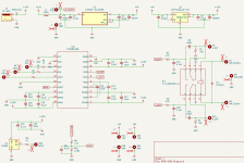
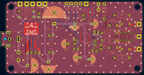
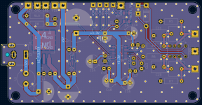
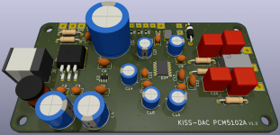
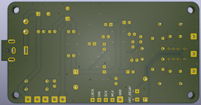


Of course notShould I give up and just buy a DAC like the Topping E30 II?
The relay to bypass filter is a good idea.
It is the voltage divisor for monitoring 3.3v from 12v for the soft mute system, as represented in the datasheet. I simply adapted the resistor values for component availability. I done it wrong ?
I need to look at the datasheet, I'll have some time on the weekend.
Thank you very much for your help !
By the way, I just realized that I had misunderstood the role of the MCLK pin, which is not used to clock the DIR9001 module. I had connected an oscillator to it in order to ensure the continuity of the operation of the DAC in the absence of an s/pdif signal, fearing that my Tripath amp would start to oscillate in the absence of a signal. But that's not how it works, and it seems that I was worried for nothing, the PCM5102A going into mute mode should be well supported by my amp.
So I'm not updating the pictures, but I'm going to delete the oscillator.
Last update, feedback would be appreciated 
So I removed the oscillator. I also changed the values of the high pass filter components, which are now 0.1uF and 50k.
I added capacitors to the relay control to minimize the influence of the coil on the analog traces, and reworked the routing of the analog section.
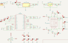
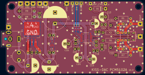
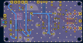
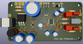
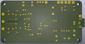
So I removed the oscillator. I also changed the values of the high pass filter components, which are now 0.1uF and 50k.
I added capacitors to the relay control to minimize the influence of the coil on the analog traces, and reworked the routing of the analog section.


Hi !
Faced with the lack of reaction on this topic, I considered abandoning my project and buying a Chinese Topping or SMSL DAC, then I noticed that many users of these DACs complain that they are not not reliable. So I decided to give my project another chance.
But I also wondered why despite the great activity on this forum, no one takes the time to answer me.
I see two reasons for this: my project is simply uninteresting, and my behavior (design first, ask questions later) is not the right one.
So I'm going to do it differently:
I'm going to redo my design from scratch, trying to do something more academic.
I will try to no longer use modules, and integrate the s/pdif receiver as well as the motorized potentiometer into my design.
For this new design, I am thinking of using an external 5V switching power supply for several reasons: to avoid a potential ground loop between the amp and the DAC due to the use of the same power supply; powering the DAC with 5V instead of 12V is more appropriate for this project, the main components only requiring 3.3V, and 5V for the volume control; the external 5v power supply being 4A, compared to the 0.5A auxiliary supply from my amp, I can put more total capacitance in my design without risking burning out the power supply.
Concerning the volume control, I am also thinking of designing the IR remote control, because it seems simpler to me to use a set of hardware-configurable IR transmission/reception components, rather than a solution based on a programmable controller and a universal remote control.
Finally, I figured that a single 3.3V rail using an LT3045 tuned with an LTC6655 voltage reference, and a huge decoupling capacitor, could easily power both the DAC and the s/pdif receiver. But then I read on this forum that s/pdif receivers, notably the DIR9001, require a dedicated LDO.
So I don't really know what to choose between a DIR9001 and a CS8416.
I also wonder how beneficial a voltage reference is for the DAC and s/pdif receiver. Are two LT3042 without a voltage reference better than a single LT3045 adjusted with an LTC6655?
For context, my source is my LG TV, connected via Toslink, my amp is a Hifimediy T1 TK2050 powered by SMSL 38V 300W and my speakers are Boston CR8, so nothing very high-end. I would therefore like my DAC to provide a significant improvement compared to my current low-end Bluetooth DAC, but without unnecessary expense.
What do you guys think about all this?
Thanks for your honesty.
I've been thinking about an alternative for several days, and I think my choice will be the ES9033Q chip.
This will obviously still not be an ambitious project, just a personal project to deepen my knowledge and get a nice little DAC that complements my current equipment well (TV as source, Tripath amp and Boston CR8 speakers).
No, this is much better.
https://www.diyaudio.com/community/threads/dac-ad1862-almost-tht-i2s-input-nos-r-2r.354078/
And find a better source. TV is not optimal choice. A small PC or streamer.
https://www.diyaudio.com/community/threads/dac-ad1862-almost-tht-i2s-input-nos-r-2r.354078/
And find a better source. TV is not optimal choice. A small PC or streamer.
Last edited:
True....this us much better.
@kiks64 You should try posting in the "digital line level" forum area. That's where most of the dac stuff is. Also there are some experienced dac-centric folks over there usually willing to help out if they can.
I understand that my choices are not optimal from a purely audiophile perspective, but I'm not sure I want to change my source for a PC. Music represents about 1/3 of my usage, my wish is not to get a system without compromise, I like the ease of use of this configuration, my current DAC is just crap and I would like an upgrade and the opportunity to design something by myself, even if it is obvious that the result will not be spectacular...
Anyway this R-2-r DAC looks incredible, and if I decide not to continue my project I could actually build it, with some compromises, I don't want a DAC that is 4 times the size of my power amp
Thank you anyway for trying to show me the way
Anyway this R-2-r DAC looks incredible, and if I decide not to continue my project I could actually build it, with some compromises, I don't want a DAC that is 4 times the size of my power amp
Thank you anyway for trying to show me the way
Your best choice is the AD1862 or AD1865, with shift registers and add a Chinese SPDIF receiver and an Amanero USB/I2S card. It works up to 24 bits/192kHz (AD1862) or 24 bits 384kHz (AD1865) Then you have all digital inputs (USB/SPDIF/TOSLINK). I even added a Bluetooth receiver with SPDIF output to one free SPDIF input. You also have a cheaper option with the AD1865 (Pavouk NOS DAC). If you need links to all those Chinese cards, or Pavouk DAC, let me know and I'll send them to you. Everyone is delighted with how it plays.
Here you have pictures of those DACs that I made, there is almost everything, Miro NOS DAC, Pavouk NOS DAC, Bluetooth version with Pavouk AD1865, USB version with Pavouk AD1865 and various full versions of Miro DACs with many DAC chips and JLS I2SoverUSB & AK4118 boards. Most of them are in the form of prototypes for testing, and I packed some in metal boxes. I am currently preparing the box for the Miro PCM63 DAC. The text is Serbian, use Google translate.
https://www.hi-files.com/forum/index.php?/topic/40702-ad1865-dac-blast-from-the-past/
https://www.hi-files.com/forum/index.php?/topic/40702-ad1865-dac-blast-from-the-past/
Last edited:
- Home
- Design & Build
- Electronic Design
- DAC design based on PCM5102A