So cleanMade a change to my NOS PCM63 DAC - swapped Sowter 9705 line output transformers to Audio Feast Finemet line outputs, 10K:600ohms. Output stage uses either E182CC / 5687 / 7044 with sections paralleled. Also changed the top plate for a two-tone color scheme.
Great job. Need a perspex cover so that you can see the beautiful work inside!
I didn't, no.@percival007: Did you implement DEM clocking?
I’d be interested to hear your comments on how they compare in terms of sound quality.
I tried a DEM PCB in this design, and another 1541 DAC I have made and it caused distortion, much like zero-crossing distortion in a Ladder DAC, weirdly.
It could clearly be heard and monitored at very low level output.
Not a big fan of it really. No mention of DEM re-clocking is made on the Datasheets so I prefer to leave it 'as intended' !!!
P
Different.
To compare the two is why I made them. They're very similar designs, apart from the DAC chip.
The 1540 is exceptionally good. You don't miss those two bits !!!! lol. Nice and detailed, very controlled, tight bass, very different from many implementations in CD Players which can tend to sound a little 'wool-y' to me. With a very sweet yet detailed top end.
But, it's no TDA1541 !!!!
That's so smooth yet refined, detailed and with a mid-range to die for. Amazing bass extension but not over-blown.
P.
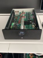
Streamer and DAC are completely finished.
More info: https://www.diyaudio.com/community/threads/dac-gallery.166807/page-22#post-7626581
Front panel is same HPL plate as rest of my system.
Mainsfilter: top right has to move to make place for this streamer.
More info: https://www.diyaudio.com/community/threads/dac-gallery.166807/page-22#post-7626581
Front panel is same HPL plate as rest of my system.
Mainsfilter: top right has to move to make place for this streamer.
Attachments
My personal MK3 DAC is almost finished but working fine already. Waiting for the frontpanels from FPE for final assembly....
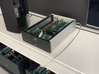
It is a setup with I2S-Streamer and DAC separated
The Streamer is based on RPI5 with Gentooplayer as Roon Endpoint.
The I2S signal is running through a FiFoPi
The I2S Signal has two outputs: BCK/LR/DATA over BNC and via Ians HDMI transmitter.
Display is based on RPI3B and Ropieee. Is recognized as extension by Roon
The DAC itself is set up as follows:
HDMI-Receiver, WaveIO and BNC inputs
I2S Switch
FiFoPi Q7 (in the pictures with standard XO for test. Final version with SinePi and Andrea Mori clocks
Dirty 5 Volt section with linearPI and 5V UC Conditioner
Clean Side FiFoPi with UC Pure 3.3V
DDDAC1794 MK in double mono setup
DDDAC MK3 PSU with AE-Chokes in both analog and digital section
Sowter Transformers as output
Attachments


Streamer and DAC are completely finished.
More info: https://www.diyaudio.com/community/threads/dac-gallery.166807/page-22#post-7626581
Front panel is same HPL plate as rest of my system.
Mainsfilter: top right has to move to make place for this streamer.
Very nice. Well done.
Ehi I've got a working dac too ")
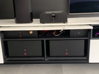
Not a professional photographer I know.
There's a Iancanada receiverpi ddc, fifopiq3, russian gk154 11-12MHz clocks, reclockpi, monitoripi pro stack underneath a single dddac board, few transformers (7? lost count) and a single 6SL7 valve output stage, coming directly from the Starship Troopers movie!
Attachments

I would like to share a project I finished a month ago. It is a DDDAC based NOS dac, but I made a few changes, mostly in the digital area and power delivery.
I finally enjoy music on low volume and hear everything that needs to be heard.
All boards are 4 layers with controlled impedance and impedance-matching resistors.
Very wide copper fills are used for the supply rails.
The two internal layers are only used for ground.
Analog and digital areas are separated as much as possible.
All traces are as short as possible.
The front and back panels are made of aluminum-core PCBs.
Transformers are custom-made:
Analog part:
Digital part:
Total BOM cost was around 600€.
Note: This is only built for my private use. I work as an embedded hardware engineer and I love electronics and music.
I finally enjoy music on low volume and hear everything that needs to be heard.
All boards are 4 layers with controlled impedance and impedance-matching resistors.
Very wide copper fills are used for the supply rails.
The two internal layers are only used for ground.
Analog and digital areas are separated as much as possible.
All traces are as short as possible.
The front and back panels are made of aluminum-core PCBs.
Transformers are custom-made:
- 50% Bigger core than needed
- 20% more turns on the primary and the secondary
Analog part:
- No LDO - direct 8V supply from custom-made Salas shunt UBiB V1.3
- Panasonic ECPU 100n film capacitors
- Vishay MELF I/V resistors
- Cinemag CMLI 15/15B transformers integrated on the PCB
- Three position switches on the back panel to change the load resistance of the Cinemags
- Dual PCM1794A per channel
- Single electrolytic capacitor for power supply decoupling - because they interfere with shunt power supply regulation in a bad way. They dominate the supply characteristics
Digital part:
- DAC is the master with two Accusilicon AS318-B clocks
- XING U30 USB-I2S board - forced to I2S slave mode, with TPS7A4700 pre-regulator (5V from USB to 3.8V)
- Galvanically isolated I2S signals
- Double flip-flop reclocking
- LMK1C1106 BCK distribution buffer
- LMK1C1102 MCLK buffer - to supply the USB-I2S board
- 5V supply from custom-made Salas shunt UBiB V1.3
- 10x TPS7A2033 LDOs - 6 of them have shunt resistors because of the low power consumption
- 0402 decoupling capacitors
- Panasonic ECPU 100n film capacitor for clock decoupling
- Separate flip-flops for left and right data channels
- Polymer decoupling capacitors
Total BOM cost was around 600€.
Note: This is only built for my private use. I work as an embedded hardware engineer and I love electronics and music.
Attachments
-
 IMG-20240528-WA0012.jpg177.7 KB · Views: 33
 -
 IMG-20240528-WA0007.jpg209.5 KB · Views: 29
 -
 IMG-20240528-WA0008.jpg98.2 KB · Views: 29
 -
 IMG-20240528-WA0003.jpg301.1 KB · Views: 33
 -
 IMG-20240528-WA0004.jpg427.9 KB · Views: 35
 -
 IMG-20240528-WA0005.jpg248.5 KB · Views: 37
 -
 IMG-20240528-WA0011.jpg230.7 KB · Views: 33
 -
 IMG-20240528-WA0010.jpg173.1 KB · Views: 33
 -
 IMG-20240528-WA0009.jpg210.5 KB · Views: 30
 -
 IMG-20240528-WA0016.jpg256.4 KB · Views: 31
 -
 IMG-20240528-WA0015.jpg197.3 KB · Views: 25
 -
 IMG-20240528-WA0014.jpg258 KB · Views: 26
 -
 IMG-20240528-WA0013.jpg123.3 KB · Views: 30
 -
 Screenshot_1.png321.1 KB · Views: 32
 -
 IMG-20240528-WA0006.jpg377.2 KB · Views: 33
You can actually get better clocking with external clocks, much better. When they are on the USB board, the clocks typically get buffered by the CPLD chip. Thus you have the jitter of the CPLD and its local LDO power affecting the sound. Thread of possible interest related to one possible approach to better clocking: https://www.diyaudio.com/community/threads/general-purpose-dac-clock-board.413001/DAC is the master with two Accusilicon AS318-B clocks...
Thanks for the link.You can actually get better clocking with external clocks, much better. When they are on the USB board, the clocks typically get buffered by the CPLD chip. Thus you have the jitter of the CPLD and its local LDO power affecting the sound. Thread of possible interest related to one possible approach to better clocking: https://www.diyaudio.com/community/threads/general-purpose-dac-clock-board.413001/
I read many forums regarding external clocks and thought that an external clock would be better, but the cost is too high.
I planned to use one buffer per clock but feared that this buffers will make the clocks noisier, especially for very short distances.
The clocks go to the flip-flop and buffer for the USB-I2S board (the buffer even has a series input resistor) with very short traces, and I took care of clock return currents. I hope that this will partially compensate for the lack of the external clock.
The current consumption of the flip flop is 10uA, and for the buffer is 50uA. Do you think this is too much for the clock?
Do you think that if I spend another 600€ just for clocks that it will make my DAC much better?
You don't need to the very best clocks to make a real improvement. The Clock Board has a cost for the parts and the PCB, which is as yet unknown. But some of the caps aren't cheap unless you can get the kit from Digikey. https://www.digikey.com/en/products/detail/rubycon/1189-4323-KIT/9817213
As far as clocks go, you can use Accusilicon 318-B and it will be better than if they are on the USB board. You can also upgrade to considerably better Iancanada clocks, which go for about $180/each plus shipping. If you only use one clock most of the time, say, maybe for playing CD rips, then maybe you would only want to upgrade one clock. Beyond that there are even better, IMHO, Andrea Mori (TheWellAudio) clocks and or AckoLabs clocks. Its possible to spend over $1,000 on clocks alone but for many people it would be great if they could get even one Iancanada clock plus a clock board. Nice thing is upgrades can happen over time, whenever there is some budget for it. Also, the clocks will be good enough they can be used for the next dac, and then for next one after that.
As far as clocks go, you can use Accusilicon 318-B and it will be better than if they are on the USB board. You can also upgrade to considerably better Iancanada clocks, which go for about $180/each plus shipping. If you only use one clock most of the time, say, maybe for playing CD rips, then maybe you would only want to upgrade one clock. Beyond that there are even better, IMHO, Andrea Mori (TheWellAudio) clocks and or AckoLabs clocks. Its possible to spend over $1,000 on clocks alone but for many people it would be great if they could get even one Iancanada clock plus a clock board. Nice thing is upgrades can happen over time, whenever there is some budget for it. Also, the clocks will be good enough they can be used for the next dac, and then for next one after that.
Thank you for the detailed answer!You don't need to the very best clocks to make a real improvement. The Clock Board has a cost for the parts and the PCB, which is as yet unknown. But some of the caps aren't cheap unless you can get the kit from Digikey. https://www.digikey.com/en/products/detail/rubycon/1189-4323-KIT/9817213
As far as clocks go, you can use Accusilicon 318-B and it will be better than if they are on the USB board. You can also upgrade to considerably better Iancanada clocks, which go for about $180/each plus shipping. If you only use one clock most of the time, say, maybe for playing CD rips, then maybe you would only want to upgrade one clock. Beyond that there are even better, IMHO, Andrea Mori clocks and AckoLabs clocks. Its possible to spend over $1,000 on clocks alone but for many people it would be great if they could get even one Iancanada clock plus a clock board. Nice thing is upgrades can happen over time, whenever there is some budget for it. Also, the clocks will be good enough they can be used for the next dac, and then for next one after that
I am 26 years old, I guess I have enough time for better clocks😂
Kudos for making a DIY DACAnalog part:
- No LDO - direct 8V supply from custom-made Salas shunt UBiB V1.3
- Single electrolytic capacitor for power supply decoupling - because they interfere with shunt power supply regulation in a bad way. They dominate the supply characteristics
.But like Markw4, I have a couple of suggestions, I'm also thinking of doing a similar DAC, but I'll put the shunt regulators on the same PCB next to the PCM1794, two for each. For decoupling capacitors put OS-CON (around PCM1794), they work without problems with Salas shunt.
Thanks! Good luck with the new DACKudos for making a DIY DAC
But like Markw4, I have a couple of suggestions, I'm also thinking of doing a similar DAC, but I'll put the shunt regulators on the same PCB next to the PCM1794, two for each. For decoupling capacitors put OS-CON (around PCM1794), they work without problems with Salas shunt.
Yes of course. I hope that a comment here an there didn't hurt anybody😃can we keep this a gallery? thanks
- Home
- Source & Line
- Digital Line Level
- DAC gallery