I'm building a dipole CBT with planar elements. My first one used the full range SB65WBAC25 which is an amazing driver but it isn't the best dipole above 2 khz. So I'm tinkering with going multiway with dedicated woofers and using planar drivers in the midrange and upwards.
The current "best" I can do is to have a midrange like the GRS PT6825 + tweeter like the GRS PT2522. It works but it is kinda wide and I would rather have a single element that can cover 400-500 hz and upwards than having a crossover in the 1-2 khz range.
Hence my funny ideas of DIYing my own planar elements. Technically I could use curved drivers but they would be more difficult to manifacture so the current idea is to build lots of small ones. My ideal driver would have ~ 64x64 mm outer dimensions, up to +- 0.25 mm xmax such that 24 of them can be crossed at 300-400 hz while playing up to 100 dB @ 1 m. It doesn't have to be as efficient as an off the shelf planar, it is OK as long is it is not less efficient than the SB65 so 82 dB / W @ 400 hz and upwards would be fine.
But I've been hesistant to try because I'm not sure I can build say 50 elements with high enough precision that they would be good enough to not just waste my time. So I've been looking at eliminating hand build parts.
The tools I have at my disposal is a wood workshop + a 3d printer. I am planning to mainly use the 3d printer to build the drirvers since I would need high consistency across all the drivers.
Based on the other drivers my one would be slightly different from the norm in 2 major areas so here I want to hear your thoughts:
1. The membrane using a flexible PCB
I think I would have great difficullity to create 50 close to identical membranes if I had try to etch them all and then make holes by hand. Hence I have looked at the copper traced flexible PCB options. https://www.diyaudio.com/community/members/wrinex.10397/ has experimented with them and found them undesirable since the copper is heavy but since his video series but the question is if it would be good enough for my use-case since I don't need as high efficiency as a regular planar. Also, is it now possible to buy thinner PCBs from say PCBWay which offers 25μm kapton base with 9μm copper so significantly thinner than what he tested which based on the JLP options probably was ~ 110μm with 12μm copper.
2. Low fs with semi high xmax in a small format
Since it would need to be able to use +-0.25 mm xmax in a small format I think I would need to be creative to allow the foil to flex. My idea is to print a surround made of TPE and then use corrugation on the foil to make it stiff without stretching.
In the end my question to you all is does this project make sense or is it doomed to fail?
the flex PCB from JLCpcb could work as a midrange, but you lose quite some output due to its weight. copper.... is a bit to heavy. if you make one be sure to NOT include the solder MASK on both sides or the foil becomes insane thick and heavy, i made a video where i made one tweeter and that loses big time to a regular mylar foil. but it works fine just much lower output. besides that i do not like the sound of kapton but maybe because its this heavy it might not show up (the wrinkle of the foil is uglier then from mylar.)
i used a double sided foil because its cool you can let the coil dive to the other sides clear the returns and have the connections points where you want them, or you could do double coil, increasing the amount of turns to win back 3 dB
i used a double sided foil because its cool you can let the coil dive to the other sides clear the returns and have the connections points where you want them, or you could do double coil, increasing the amount of turns to win back 3 dB
Yes, I have looked at your video series on the flex pcbs and they were informative, thank you for putting up your videos! ❤️
I do have question about kapton + copper weight vs efficiency vs other characteristics. Say I have 2 pcbs with a coil where trace width is matched such that the end impedances are identical but the total thicknesses are different:
If 1 is more efficient than 2, does that mean that the golden rule to have as little aluminum / copper as possible as long as it is thick enough to handle the expected amount of power without damaging the traces?
I do have question about kapton + copper weight vs efficiency vs other characteristics. Say I have 2 pcbs with a coil where trace width is matched such that the end impedances are identical but the total thicknesses are different:
- 50μm kapton + 12μm copper
- 100μm kapton + 2x12μm copper (dual sided)
If 1 is more efficient than 2, does that mean that the golden rule to have as little aluminum / copper as possible as long as it is thick enough to handle the expected amount of power without damaging the traces?
hmm sorry i really cant tell you with so many parameters  in general light as possible. when you want top end. even then sometimes they measure ok to 16 khz (for a tweeter, like in the video) they might still sound poo. if they are to heavy. i would go for 50 um everyday for a mid. having twice the weight of the foil but dual coil. might not outweight each other above a certain frequency due to the weight. where and how much i could not tell.
i normally use 12 miccron mylar for mids and maybe 30 micron alu ... max.. so there is a pretty huge difference. by the way 12 micron can be4 used for everything so far
in general light as possible. when you want top end. even then sometimes they measure ok to 16 khz (for a tweeter, like in the video) they might still sound poo. if they are to heavy. i would go for 50 um everyday for a mid. having twice the weight of the foil but dual coil. might not outweight each other above a certain frequency due to the weight. where and how much i could not tell.i normally use 12 miccron mylar for mids and maybe 30 micron alu ... max.. so there is a pretty huge difference. by the way 12 micron can be4 used for everything
so farAlright.
The consideration was mainly thinking about cost when prototyping:
The cheapest and thinnest flexible PCB option I've found is JLCPCB which offers:
110μm kapton + dual 12μm copper layers
or
70μm kapton + single 18μm copper layer
PCBWay is 5-10x as expensive but offers thinner options:
25μm kapton + 9μm copper layer.
If less weight is better then I'll probably first do the single layer JLCPCB since it is cheap enough for me to make mistakes and iterate without hurting my wallet too much. But then if I get satisfied then I guess it would be worth doing a run from PCBWay with their thinnest option. If we assume that 50% of the membrane area is covered by alu / copper then it is only 31% heavier than your midrange membrane which is pretty close all things considered.
Napkin math:
Kapton = 1420 kg / m3
Mylar = 1400 kg / m3
Alu = 2710 kg / m3
Copper = 8850 kg / m3
((1420 * 25) + (9 * 8850 / 2)) / ((1400 * 12) + (30 * 2710 / 2)) = 1.31
yeah biggest issue is copper if it works out for you i dont know it all depends on the magnets used and the goals you want to achieve... how high you can cross it ,efficiency etc.
i am not sure if your math is correct. the biggest bulk is the coil. and yours is 3 times as heavy.
another thing is, there glue, there is no mention of it but its there also on my alu. except they have a laminate, so after etching all glue used is still there. on my coil the glue is udner the coil. where there is no coil there is nog glue
if there foil is 50Micron including gleu that would be nice.
if it works out for you i dont know it all depends on the magnets used and the goals you want to achieve... how high you can cross it ,efficiency etc.i am not sure if your math is correct. the biggest bulk is the coil. and yours is 3 times as heavy.
another thing is, there glue, there is no mention of it but its there
also on my alu. except they have a laminate, so after etching all glue used is still there. on my coil the glue is udner the coil. where there is no coil there is nog glueif there foil is 50Micron including gleu that would be nice.
Last edited:
Looks like it
Say if I skip using the flexible PCB and try to make a kapton / mylar + alu membrane instead: is there a simple way to make the alu traces without requiring too specialized tools? Is etching the way to go or is there a more simple way? I stalked your youtube channel and as far as I can see you seem to have tried a lot of different methods.
Say if I skip using the flexible PCB and try to make a kapton / mylar + alu membrane instead: is there a simple way to make the alu traces without requiring too specialized tools? Is etching the way to go or is there a more simple way? I stalked your youtube channel and as far as I can see you seem to have tried a lot of different methods.
If the info on this site is correct http://www.integracoustics.com/MUG/MUG/articles/planar/
which discusses the formula for planar drivers:
F = I L × B
F = Force on the wire
L = length of wire that carries the current subjected to ...
B = the magnetic field
I= the current through the wire
L × B = the Thiele-Small “Bl” product given for raw drivers
If it is correct then it looks like current + loop length is king and the way to maximum efficiency would be to make the trace crossection area as small as possible while not being damaged at the target power handling and then add as many traces of that width as possible. And that if max power handling is reduced then in theory you could reduce the trace width for more power.
That is interesting because then the PCBWay option would probably perform pretty well. It wouldn't have the same power handling as 3x as thick alu traces given the same weight but I would probably only need 1W max peak per driver if it is efficient enough so that wouldn't be a problem.
in short, get as much turns in there and keep impedance the same. every doubling of turns while impedance remains the same is + 3 dB , so 10 traces 20 traces 40 traces 80 traces etc, this is why bass or lower mid still works fine if not better if you wan to to put in the work for alu magnet wire
Makes sense.
I did some more napkin math and given the goal of maximum of coil turns then the thicker JLCPCB probably isn't too bad. It has 2 layers of 33% thicker copper than the thinner PCBWay one so if I naively assume that I can cram 33% more turns with the thicker copper then the ratio of coil turns / weight is just 31% higher on the expensive PCBWay PCB when compared to JLCPCB dual sided which isn't that much of a difference all things considered.
Definently worth trying! And with a dual sided PCB I could make the coil transition with a via in the middle and then turn outwards again letting me have the connection points beside each other at the bottom without having to solder a jumper wire.
And while it might not be the best tweeter ever I'm OK with that. I only need it to be a better tweeter than the SB65 which shouldn't be that hard with a symmetric planar since the SB65 falls apart and stops radiating to the rear at 8 khz
Napkin math for turn to weight ratio:
weight of 40μm + 50% 9μm copper = ((1420 * 25) + (9 * 8850 / 2)) = 75325
weight of 110μm + 2x 50% 12μm copper = ((1420 * 110) + (2 * 12 * 8850 / 2)) = 262400
amount of turns of single 9μm vs dual 12μm ~ 12/9 * 2 = 2.666666
turn to weight ratio = (262400 / 75325) / 2.666666 = 1.31
The "turn to weight ratio" isn't enough for estimating, only when the resistances are same (see Wrinex #9).
If the frequency is low, and radiating surface is large, the efficiency increases with volume (mass) of conductive material, but decreases the high freq. extension.
The membrane movement's profile is determined by acoustical load, if the frequency is low, and radiating surface is large (for example planars woofer). If you takes to membrane double volume of conductor, the B*l will 1,41times more at same resistance, and you win 3dB efficiency.
About the tweeter's mass and efficiency coming soon.
The tweeter operates higher frequncies and it's relative small. The moving mass is near alone the membrane mass, the coupled moved air mass is relative and absolutely smaller (due to freq. and dimensions). If the acoustical coupling isn't total (at bottom of freq. range), two major effect can dominate: the driving force must be enough for feed to acoustical load, and the mass acceleration's force request requires mass as lower as possible. The optimum thickness of line sorce pure ribbon is between 3-9 micrometers, depending on length of transducer. The long line source produces essentially 10dB/decade rising of response, which can compensate partially the elemental ribbon-sections's roll off. The small total ribbon or planar supertweeters haven't tis compensation mechanism. These contain thinner alufoil, but - as compensation - more induction at membrane.
In summary: the planar woofers efficiency is better, if the conductor volume bigger (not ad infiniti). At small tweeters (at its frequency range) generally have worse efficiency with thicker conductor. These are only tendencies, the actual result depends a lot of circumstance. However, the 110μm kapton plus 2*12μm copper will be well beyond the optimum values for tweeters at any circumstances.
In summary: the planar woofers efficiency is better, if the conductor volume bigger (not ad infiniti). At small tweeters (at its frequency range) generally have worse efficiency with thicker conductor. These are only tendencies, the actual result depends a lot of circumstance. However, the 110μm kapton plus 2*12μm copper will be well beyond the optimum values for tweeters at any circumstances.
Please remember that copper traces on PCBs have a limited current carrying capability, while you should be quite safe for your use case it doesnt hurt to check:
https://www.digikey.de/en/resources/conversion-calculators/conversion-calculator-pcb-trace-width
Attached is an example calculation for 12um copper and 60mm length, your trace width would have to be about 0.5mm per amp. Ohmic resistance of that trace is 0.18 Ohms.
Hope this helps, interesting project!
Attachments
However, the 110μm kapton plus 2*12μm copper will be well beyond the optimum values for tweeters at any circumstances.
Probably. Interestingly enough Radian seems to have used a heavy 120μm foil in their LT2 tweeter, if the markings are correct so while thinner is probably better it would hopefully be good enough.
And I did some rough calculations with an equivalent calculator like https://www.digikey.de/en/resources/conversion-calculators/conversion-calculator-pcb-trace-width
Given max 10 degrees of change, 25 degree ambient temperature then I might get away with as thin as 0.38 mm thick traces, and with ~ 300 cm of trace for each 6x7cm driver that should roughly equal 10 ohms. It would have be able to handle 0.5 A so 5W which is plenty for my use case.
An issue with the off the shelf planars is that they copy the BG Neo3 PDR where they have fewer sets of magnets which isn't good for my dipole use case since the improved off axis dispersion causes a dipole null. So my current plan is to have magnets across the whole width of the planar to avoid this.
I wasn't planning on using a pole piece since metal is more annoying to work with but seems to perform well enough without it as found by @WrineX. My current plan is to use small 50x3x3mm N35 magnets.
So with a 7 cm wide and 6 cm high planar I'm thinking I can cram 8-10 magnets along the 6 cm height (my planar would be flipped sideways compared to most planars. And I'm thinking of corrugating the flex PCB like @WrineX has done and then only mounting it on the sides. I'm not sure how much slack is needed for the pcb to flex fully to +- 0.5mm xmax, if 1cm margin on each side is enough or if more is needed but I guess I will just have to try and see how it works.
I'm currently toying around with the PCB layout since I can adjust all the other parts easily. I'll also have to think about how deep I want the corrugations to be and design a 3d printable corrugating mill to match. @WrineX has very deep corrugations but the Radian LT2 and BG Neo10 corrucations seem to be very shallow. I can't have them too deep since that will probably mess up the xmax but say 2 mm peak to peak might be enough to stiffen the flex PCB. Or maybe 1 mm is enough.
Or if instead of having a rolling corrugation mill I should make molds and then press and stretch the corrugations on a flat foil. Would probably work well with smaller corrugation patterns but will probably stress the PCB too much if I go too deep.
Last edited:
You can give more than 10 C-degrees, because the kapton and kapton-copper conjunction have excellent thermal ruggedness. Furthermore, the music's crest factor helps, "stand by you". And remember, we are talking larger heat dissipation surface area, than most of woofer's.Given max 10 degrees of change, 25 degree ambient temperature then I might get away with as thin as 0.38 mm thick traces, and with ~ 300 cm of trace for each 6x7cm driver that should roughly equal 10 ohms. It would have be able to handle 0.5 A so 5W which is plenty for my use case.
You can give more than 10 C-degrees, because the kapton and kapton-copper conjunction have excellent thermal ruggedness. Furthermore, the music's crest factor helps, "stand by you". And remember, we are talking larger heat dissipation surface area, than most of woofer's.
Possibly. I did some calculations for 0.15 mm trace width since JLCPCB has high enough precision to handle it which would net twice as many windings of the coil. The impedance would be annoyingly high at ~ 56 ohms but still workable in my case since I can connect multiple in parallell in the shading network to reduce the impedance seen by the amp.
While I might start at 0.38 mm if I get a design I'm satisfied with it might be worth doing a run with 0.15 mm trace width and then ramp up the current and see how much it can handle until it burns 🔥. If it can still handle say 3W then it would effectively be free efficiency since it's output at 3W should match or exceed the thicker traces at 5W.
Or if you all think it's a good idea I might start with 0.15 and go bigger if it burns too easily. 0.15 mm traces @ 5W would bump the temperature by 12 degrees in above mentioned calculator.
Last edited:
I'm thinking about how to get enough xmax without overcomplicating things.
I can do the above mentioned idea of 6 cm tall 7 cm wide drivers. But I'd probably have to do some fancy suspension of the membrane to allow enough xmax since they are quite small. Although I could probably get by with reducing the xmax requirement to +- 0.25 mm that is still more than normal for the size.
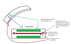
Or I could scale it up to say a 20 cm tall 7 cm wide driver but curved to fit on my CBT (0.75 m radius). With a much bigger driver I wouldn't need fancy suspensions since it would be big enough to naturally go down to 400-500 hz. If anything I'd probably want to tension the membrane sideways same as all the others do. In this case my main 2 questions are:
1. It should be OK to mount the magnets sideways right? instead of lengthwise along the driver? Mounting them sideways would make the curve more smooth and eliminate the magnet gaps. Also, it would be much easier for me to manifacture since the strongetst parts of my print would be the sides and then I could lean on the mechanical strength of the magnets themselves to reach across to the other side.
2. Corrugating side to side should still be a good idea even with sideways mounted magnets right?
And as a side note I'd have to try the tensioning trick @WrineX mentioned in one of his videos that one manifacturer did. Hopefully the parts would be identical enough that I would be able to get close enough tension even without individual adjustments. But in the worst case I could always size the tensioning parts individually for each driver.
I can do the above mentioned idea of 6 cm tall 7 cm wide drivers. But I'd probably have to do some fancy suspension of the membrane to allow enough xmax since they are quite small. Although I could probably get by with reducing the xmax requirement to +- 0.25 mm that is still more than normal for the size.
Or I could scale it up to say a 20 cm tall 7 cm wide driver but curved to fit on my CBT (0.75 m radius). With a much bigger driver I wouldn't need fancy suspensions since it would be big enough to naturally go down to 400-500 hz. If anything I'd probably want to tension the membrane sideways same as all the others do. In this case my main 2 questions are:
1. It should be OK to mount the magnets sideways right? instead of lengthwise along the driver? Mounting them sideways would make the curve more smooth and eliminate the magnet gaps. Also, it would be much easier for me to manifacture since the strongetst parts of my print would be the sides and then I could lean on the mechanical strength of the magnets themselves to reach across to the other side.
2. Corrugating side to side should still be a good idea even with sideways mounted magnets right?
And as a side note I'd have to try the tensioning trick @WrineX mentioned in one of his videos that one manifacturer did. Hopefully the parts would be identical enough that I would be able to get close enough tension even without individual adjustments. But in the worst case I could always size the tensioning parts individually for each driver.
Attachments
you can use magnets sideways. problems might be you have much more turning of the coil wasting resistance on parts that do no play. secondly if you want to corrugate to follow you curve better. (witch i would) you get the problem i had. havintg to know how much the coil shrinks. or else you coil will be sitting on top of the magnet or whatever.. not aligned where you thought it would be.. since your foil gets x amount smaller after corrugation1. It should be OK to mount the magnets sideways right? instead of lengthwise along the driver? Mounting them sideways would make the curve more smooth and eliminate the magnet gaps. Also, it would be much easier for me to manifacture since the strongetst parts of my print would be the sides and then I could lean on the mechanical strength of the magnets themselves to reach across to the other side.
so when ordering foils. i would not recommend that. unless you know exactly how much it shrinks. another thing is the JLCpsb things dont corrugate nice like alu on mylar does its to stiffHmm, that sounds like it would probably make it hard to dial in consistently. It is probably a better idea to just build smaller but flat drivers.
Would I want to mount and tension the membrane in both the vertical axis and horizontal or could I get away with only mounting and tensioning in the sides? My naive thought is that it would allow more xmax in the same volume since the membrane only has to stretch in a single axis + that axis is longer.

Would I want to mount and tension the membrane in both the vertical axis and horizontal or could I get away with only mounting and tensioning in the sides? My naive thought is that it would allow more xmax in the same volume since the membrane only has to stretch in a single axis + that axis is longer.
Or if it would be a better idea to just add a surround like this MCMA Planar. I should be able to print a small surround in TPU. The softest I can print is 80A which is more rigid than most surrounds but hopefully still soft enough to allow +- 0.5 mm of xmax without too much loss in efficiency.

- Home
- Loudspeakers
- Planars & Exotics
- DIY midtweeter planar with flexible PCB membrane, a recipe for disaster?