Ok, I will see what I can do. I'm gonna try out the panels on an indoor event next weekend, so will have to try to do some measurements before then to do some tweaks to my DSP.
I probably will not do polar measurements though since it is a bit of work and not so interesting information IMO since the difference between different DML speakers will be quite marginal, unless one for example builds a frame to reduce backward dispersion.
If you want to get an idea about dispersion of DML panels you can have a look at Tectonics spec sheet for DML500:
https://tectonicproaudio.com/wp-content/uploads/2022/05/DML500-Rev-07-Jan-22.pdf
But will do some on and off axis measurements at different distances at least.
@kipman725 Sure, will take some more pics. You did see the soundcheck video? That shows the panels from back and front closely. But I agree it can be nicer with pics than videos.
Was asked for some more info on how I prepare the GPS plates. While I think the hide glue with shellac combination should work well on most styrofoam, the thickness you want might vary somewhat depending on the density of the material. And perhaps for example PVA works better on some materials.
I mix 1 part hide glue granules with 3 parts water and heat in a pot in a water bath until just above 60c.
Use a paint roller and apply, making sure to roll off excess glue before rolling on the plate to get a nice even thin layer.
I missed to measure how much alcohol I added to the shellac flakes, but you want a much thinner mixture than a usual solution, probably almost 10 times the weight in alcohol compared to flakes. Soak the flakes overnight in half the alcohol, then dilute with the rest and apply in the same way as the hide glue.
Often it is recommended to use high purity isopropanol alcohol, but I just use the kind of cheap mostly isopropanol alcohol you can buy in bottles in petrol stations in red colour with horrible smell (T-Röd for the Swedes). Seems to be fine for this application...might be a bit more fuzzy when you want to make a nice french polish on furniture.
Both the hide glue and shellac should dry very quickly, so you have to work fast. If you have thin plates, you also have to be careful to avoid bending when plate dries. Paint both sides quickly after each other before they dry to minimize the risk of that happening.
I found a building preservation shop in Sweden that sells both the glue and shellac:
https://www.byggnadsvardsbutiken.se/product/hudlim-3
https://www.byggnadsvardsbutiken.se/product/schellackflingor-tn-orange100g
It is often sold by specialist shops for instrument building and restoration as well.
Managed to do some measurements, but had little time and was a bad day with a big bunch of noisy crows in a nearby tree and unusually much traffic  I hope I can get a better opportunity in the future to do better measurements, but for now this was the best I could do.
So most measurements have quite a bit of pollution, likely resulting in harmonic distortion being much higher according to REW compared to earlier measurements, and I also suspect some of the variations between FR at different distances can be attributed to that.
I had two plates hanging to the side of each other, so total plate surface 500x660 and all measurements are with 24dB 90Hz HPF, otherwise unprocessed.
Here is on axis measurement as 1, 2 and 4 meters:

45 degrees off axis at 1, 2 and 4 meters:

Averages off on axis (orange) and off axis (turquoise) :

I will do some work during the winter to smooth out the response by modifying the suspension at least, but they do handle EQ quite well. Didn't have time to do the EQ and iterate with analysis until I have a response I'm happy with now, so will hope I get some time to do tweaking at the venue next weekend.
My takeaways are first how different the FR is at different distances in the on axis measurement. When not using a HPF I have noticed deep bass is much more intense when close to the speaker, but that effect is very much diminished already at 1m and above 100Hz, at least that is how I perceived it. But in the on axis measurements at around 200Hz we see the expected 6dB difference between each response, even slightly more at one point. Then at 3k there is an even bigger gap which is a surprise which I have no explanation for at the moment. The on axis measurements for both 4m and 1m does seem quite wonky and I really have to redo them to verify they are correct.
Otherwise the typical difference between 1 and 4 meter seems closer to 8dB than the usual 12dB, but in the off axis measurements the average difference is perhaps 10dB.
So I would say that the graphs as they are does show that the sound travels further than with a regular point source, but being of questionable quality they are not really conclusive.
I hope I can get a better opportunity in the future to do better measurements, but for now this was the best I could do. So most measurements have quite a bit of pollution, likely resulting in harmonic distortion being much higher according to REW compared to earlier measurements, and I also suspect some of the variations between FR at different distances can be attributed to that.
I had two plates hanging to the side of each other, so total plate surface 500x660 and all measurements are with 24dB 90Hz HPF, otherwise unprocessed.
Here is on axis measurement as 1, 2 and 4 meters:
45 degrees off axis at 1, 2 and 4 meters:
Averages off on axis (orange) and off axis (turquoise) :
I will do some work during the winter to smooth out the response by modifying the suspension at least, but they do handle EQ quite well. Didn't have time to do the EQ and iterate with analysis until I have a response I'm happy with now, so will hope I get some time to do tweaking at the venue next weekend.
My takeaways are first how different the FR is at different distances in the on axis measurement. When not using a HPF I have noticed deep bass is much more intense when close to the speaker, but that effect is very much diminished already at 1m and above 100Hz, at least that is how I perceived it. But in the on axis measurements at around 200Hz we see the expected 6dB difference between each response, even slightly more at one point. Then at 3k there is an even bigger gap which is a surprise which I have no explanation for at the moment. The on axis measurements for both 4m and 1m does seem quite wonky and I really have to redo them to verify they are correct.
Otherwise the typical difference between 1 and 4 meter seems closer to 8dB than the usual 12dB, but in the off axis measurements the average difference is perhaps 10dB.
So I would say that the graphs as they are does show that the sound travels further than with a regular point source, but being of questionable quality they are not really conclusive.
In my garden with the centre of the frames hanging around 1.5 m above ground. Would been better to hang them higher as well as on top of each other instead of next to each other I think though.I what kind of location did you take these? The appr. 300 Hz is probably the floor bounce?
45 deg look quite nice. You didn't include any distortion graphs...
//
But I suspect the bump at 300Hz is a strong mode in the panel, which is seems typical for a panel around these dimensions. The first and second modes of both the sort and long side will easily cramp together in the lower mids, and getting them to spread out to avoid that bump is one of the main goals and challenges when designing a panel it seems.
I didn't include distortion graphs because I felt they where very unrepresentative since the distortion is much higher compared to earlier measurements I have done. I will have to try to determine if it was simply the background noise or the fact that I was driving a single plate per amp channel in 4 ohm instead of two plates in 8 ohm as before, and still getting similar SPL, so in effect driving the plates/exciters double as hard.
So until I know what is the cause of the increased distortion I would not read too much in to it, but here is the graph for the 2m on axis:
Off axis and difference distances look quite similar with about 30dB between THD and fundamental. Can also see that noise floor reaches almost 60dB.
No, like I mentioned I ordered an SPL meter so I can make absolute measurements, but it got lost in transit, so waiting for a new one :\Is the voltage/SPL calibrated?
Personally I don't have as much interest to know the absolute SPL any more after testing them in the field and knowing how they stack up together with some decent subs, but will do calibrated measurements next time hopefully.
There are a few ways to flatten the response. Varying the thickness is one way, but a lot of work and will not give the strongest effect.The frequency response could likely be very flat with some experimentation wr to varying the thickness of the panels from outside edge towards center. I wonder what might happen if one were to contour the panel to match the typical response graph but reversed.
Width and height of plate seems to be the most important factors when it comes to where the strong fundamental modes will be placed.
Plate suspension seems to have a quite strong effect and can be quite easy to modify.
One can also place weights at certain spots to dampen modes, which will have a similar effect to varying thickness.
That said, DML doesn't give a flat response by nature. The sound is built up by modes, and you can spread out the peaks those create to get an overall flatter response. But even with a prefect design, count on having to EQ those peaks down a bit if you want a flat response.
Briliant work Leob  Thanks
Really interesting to see how the off axis is much more flat. This is the opposite of a "normal" speaker. This will for sure also have a big impact on the power curve. So playing in a room, and eq'ing for a flat on axis response will give guite a lot more energy towards higher frequencies than for a traditional speaker .... interesting ....
One of the things otheres have found/reported is that rounding the corners will help reduce the edge reflection (think og waves in a pool hitting a wall and being reflected .... not sure how much this matters.
If you are using an iPhone you can download a free app called Decibel X:db Sound Level Meter. It's of course not the same as a real sound level meter, but I would think it's accurate within +- a few db ... so ok for noting if it's 90 db or 100 db .....
Measuring the impedance curve will give a good indication of modes ... have seen a measurement somewhere where you can see several distinct peaks. Could be a method to use whan trying to move or reduce modes ... easier to do an impedance measurement than a freq response.
PS. I have ordered two exciters to play with .... as said I think there is a lot of interesting features in this for the use as side and rear surround speakers in a HT.
PPS. There is a lot of good information on Tectonic's youtube channel: https://www.youtube.com/user/TectonicAudioLabs/videos e.g. the videos "The Tectonic DML Part x"
PPPS. Also you can see on this picture how they use 2 weights for damping, and that they are supporting the panel 4 places (See red circles)
ThanksReally interesting to see how the off axis is much more flat. This is the opposite of a "normal" speaker. This will for sure also have a big impact on the power curve. So playing in a room, and eq'ing for a flat on axis response will give guite a lot more energy towards higher frequencies than for a traditional speaker .... interesting ....
One of the things otheres have found/reported is that rounding the corners will help reduce the edge reflection (think og waves in a pool hitting a wall and being reflected .... not sure how much this matters.
If you are using an iPhone you can download a free app called Decibel X:db Sound Level Meter. It's of course not the same as a real sound level meter, but I would think it's accurate within +- a few db ... so ok for noting if it's 90 db or 100 db .....
Measuring the impedance curve will give a good indication of modes ... have seen a measurement somewhere where you can see several distinct peaks. Could be a method to use whan trying to move or reduce modes ... easier to do an impedance measurement than a freq response.
PS. I have ordered two exciters to play with
.... as said I think there is a lot of interesting features in this for the use as side and rear surround speakers in a HT.PPS. There is a lot of good information on Tectonic's youtube channel: https://www.youtube.com/user/TectonicAudioLabs/videos e.g. the videos "The Tectonic DML Part x"
PPPS. Also you can see on this picture how they use 2 weights for damping, and that they are supporting the panel 4 places (See red circles)
Attachments

Impedance; see first post here by xrk971
https://www.diyaudio.com/community/threads/a-study-of-dmls-as-a-full-range-speaker.272576/
.... but actually not so easy to see the relation to the frequency response as I thought ......
https://www.diyaudio.com/community/threads/a-study-of-dmls-as-a-full-range-speaker.272576/
.... but actually not so easy to see the relation to the frequency response as I thought ......

Indeed, for my initial setup I only did on axis measurements, and found that I had to keep the highs sloping off more than expected to get a sound that I think was warm but clear.Really interesting to see how the off axis is much more flat. This is the opposite of a "normal" speaker. This will for sure also have a big impact on the power curve. So playing in a room, and eq'ing for a flat on axis response will give guite a lot more energy towards higher frequencies than for a traditional speaker .... interesting ....
It doesn't seem to have that great of an effect, but is mentioned in some patents apparently.One of the things otheres have found/reported is that rounding the corners will help reduce the edge reflection (think og waves in a pool hitting a wall and being reflected .... not sure how much this matters.
Trimming the plate in any way will affect the modes somewhat, question is how much it helps trimming the shape rather than the overall dimensions. Some early DML designs was using an ear like shape.
I'm not great with all the theory and papers on DML, but will speculate a bit anyway
As I understand it is not really about waves being reflected at the edges, but the wavy wobbling of the plate which is constrained by the dimensions and material properties. So somewhat like the surface of a pool, but the bounds are not reflecting the waves but rather constricting the size of the waves.Imagine instead a steel plate you are trying to bend in a wave pattern. A 10x10 plate would not be possible to bend with a wavelength of over 10mm since the wave will not fit. If the plate is round or square will not affect the amount of force needed to bend the plate by a few degrees, nor how long waves can fit, but changing dimensions will.
So getting rid of the corners will not really spread out the modes, the plate will still vibrate in the same pattern pretty much, but will have no corners flopping which will have some effect on the response.
So I think it can be worth exploring as a tweak, but secondary to overall dimensions and suspension.
I think best way to analyse modes directly is to put sand or rice grains on the plate while lying down and playing sine waves. That will give you a visual representation of how the panel responds to different frequencies.Measuring the impedance curve will give a good indication of modes ... have seen a measurement somewhere where you can see several distinct peaks. Could be a method to use whan trying to move or reduce modes ... easier to do an impedance measurement than a freq response.
I haven't tried it out myself yet, but will probably do when I take some time for tweaking the suspension and perhaps dimensions of my plates.
I looked at those, but not sure I feel it is worth the investment compared to a SPL meter? I guess the advantage is much better accuracy compared to an SPL meter in the same price range?The way to get calibrated measurements is to use a microphone calibrator it fits around the tip of the measurement mic and generates a 1khz tone at a known SPL. This one is the cheapest available that works with the ecm8000.
Was hoping that a cheap SPL meter would be good enough as reference, but I guess their typical +-2dB accuracy is a bit useless.
I looked at those, but not sure I feel it is worth the investment compared to a SPL meter? I guess the advantage is much better accuracy compared to an SPL meter in the same price range?
Was hoping that a cheap SPL meter would be good enough as reference, but I guess their typical +-2dB accuracy is a bit useless.
You can calibrate your mic and also use it as an SPL meter. Quite often you need to monitor SPL when doing gig/festival work in the UK due to offsite noise restrictions, adjacent stage bleed etc. As the cheaper calibrators are only class 2 and cheaper measurement mics start to compress >120dB this isn't 'perfect' but from my experience using an ECM8000 and this calibrator my results are very close to and track any expensive metering that has been brought to FOH. This is very useful as you can then define numerical limits that you can follow. Cheap SPL meters won't have measurements like Leq(z) which are often what people will want you to follow. The next step up would be a class 1 calibrator and a measurement mic that could handle higher SPL but this is expensive.
The main advantage of using a calibrator for me though in speaker development is that I can take measurments and have them be comparable to other measurments I took at different times. If I measure at 2m/2.83V with a calibrated mic and record how I took that measurment I can easily use with another measurment I took another day.
Sooo I've been playing with this... after battling with Tectonic exciters, and multiple variations of substrates and laminates, I've eventually settled on 20mm EPS with paper skins which sound kinda ok.
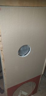
The screen-shot shows FR curves for two panels sized 460 x 770mm and measured nearfield (50cm). The panels are fixed, undamped, on their long sides, and the short sides are unsecured. The drivers (one only per panel) themselves are bolted into a stay, and mounted on 100m dia polycarb discs behind a 105mm hole cut out of the EPS. Three blobs of hot-glue secure the polycarb discs to the EPS. The paper skins are the only damping.
As the other pic shows, I WAS going to do a hybrid open-baffle with a 15" high-Qts driver for the extreme lows, but the slight bass loss vs better dynamics and definition (without the cross-over and additional woofer) is a no-brainer. So these curves are for the panel only.
The difference between the curves is due to the amount of glue used to secure the paper to the EPS. The panel with the flatter response (blue) weighs about 240g in total, and t'uther (red with the peak at 3k) is about 290g. Too much glue...
Next step: Drive this baby with 4 exciters per side and see if I can use it for live gigs. Each panel SHOULD handle around 160WRMS. And at around 99dB/W sensitivity per panel, this translates to over 119dB when driven at 300W peak.
I suspect that the EPS/paper laminate might not handle so much ferocious abuse for 3 or 4 hours at a time. In which case I might have to revert to polycarb twin-wall panels, and a bit of EQ.
Whaddaya tink?
Attachments
Last edited:
Zeess von?Nice! Can you please post distortion graph for the blue trace?
//
- Home
- Live Sound
- PA Systems
- DML PA systems