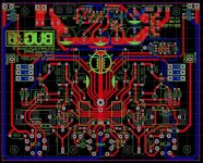
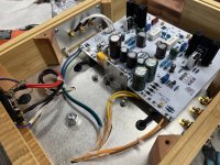
Wanted to share this circuit I’m working on. Cascode output is somewhat unusual and it’s an easy way to get into A2. I just finished the breadboarding and testing/tweaking. I spent a few days designing PCBs and I’ve just ordered some. I’ll post some updates here once I get the PCBs populated. Then I’ll be designing the chassis. Let me know what you think.
Attachments
-
 Fin V2.3 with PS_Original.jpeg289.6 KB · Views: 551
 -
 10W_Original.jpeg215.9 KB · Views: 514
 -
 9W_Original.jpeg221.7 KB · Views: 200
 -
 5W_Original.jpeg217.4 KB · Views: 180
 -
 1W_Original.jpeg262 KB · Views: 185
 -
 FR vs Power 1-10W_Original.jpeg221.6 KB · Views: 241
 -
 Screen Shot 2024-04-05 at 2.00.31 PM_Original.jpeg551.2 KB · Views: 525


Wow!
I need to get somebody local who can do the building part of my projects, and make them look as good as your amplifier.
I am interested in how well your Cascode circuit comes out.
Generally, cascode circuits cause the top device's output impedance to increase (in this case, the EL34's Triode Wired plate impedance, rp, will become high impedance).
But with the two negative feedback loops, at least that will cause the EL34's plate impedance to be reduced again.
The question is, with the cascode circuit plus the negative feedback . . . Will the triode wired EL34's plate impedance end up higher than, or end up lower than, the approximate plate impedance of 1,250 Ohms that you get with a non-cascode triode wired EL34 with no other negative feedback.
suitable for EI34 KT88 FU7 FU50 6P3P, inductance 41HCan you post a link of those OPT? Thanks
https://a.aliexpress.com/_mPTPstu
All true, the cascode takes the already very large Z of the MOSFET drain and multiplies that by the gain of the output tube then adds that to the plate Z. So you do end up with a naturally pentode like Z driving the output transformer. Luckily the MOSFET also has gain that can then be used to add a bit of feedback to allow the plate to respond to the voltage drop that would typically result from a non infinite output transformer inductance.Wow!
I need to get somebody local who can do the building part of my projects, and make them look as good as your amplifier.
I am interested in how well your Cascode circuit comes out.
Generally, cascode circuits cause the top device's output impedance to increase (in this case, the EL34's Triode Wired plate impedance, rp, will become high impedance).
But with the two negative feedback loops, at least that will cause the EL34's plate impedance to be reduced again.
The question is, with the cascode circuit plus the negative feedback . . . Will the triode wired EL34's plate impedance end up higher than, or end up lower than, the approximate plate impedance of 1,250 Ohms that you get with a non-cascode triode wired EL34 with no other negative feedback.
How it exactly compares to a simple triode plate Z I’m not sure but it’s in the ballpark. How can I tell? Because the measured output Z at the output transformer secondary is in a very typical range.
Very nice work. ")
Not knocking your effort. Always good to try out new ideas.
Cascode Output with Mosfet drive being foremost.
The Cascode normally provides high gain and high output Z. But the final power loading on the tube will be killing the gain here. The tube output current accurately reflects the Mosfet drive current, which is square law. The N Fdbk from the OT secondary to the Mosfet Source -will- largely linearize the Mosfet driver and lower the output Z. It has the high gm of the Mosfet to enforce that fortunately, but does not make full use of the front end gain like a typical global Fdbk. Usually, N Fdbk thru the OT is what designers would like to avoid if possible, due to OT phase issues.
The resistive "Schade" like Fdbk back to the input tube plate would seem to be substituting for the global loop here, but it is loading down the input triode's plate. So the psuedo "global" reference is somewhat distorted. This gets passed on to the Mosfet for final output reference signal. Resistive "Schade" is usually best left to an inner loop so the normal global can fix it's flaws.
Unless: (cosmic music playing)
UnSet (or variants of) are used to separate the Fdbk and drive functions of Resistive "Schade" Fdbk. (having the Fdbk connected to the driven device distorts the current coming back thru the Fdbk resistor) UnSet isolates these.
UnSet also increases the power output of the tube, since effective B+ is increased when max current is demanded. No need to go to A2 operation normally, but is possible to do. (driver and output device power add with cathode drive)
A2 operation of EL34 for more power? As long as you are buying the tubes.
Well, just a couple of simple changes suggested. Change the Mosfet to a P-channel follower, with a minus 50V supply for the drain.
Skip the OT secondary N Fdbk, unless going back to the input triode for extreme low output Z. And move the resistive "Schade" path to the output tube grid1 and then to ground (an R divider from output tube plate to ground, no connection to the input triode plate ). (so UnSet mode) The UnSet'd output tube becomes highly linear and low output Z.
Just to illustrate:
A 6HJ5 Beam tube in normal pentode mode,
then the 6HJ5 in UnSet mode. Extreme linearity, good power, low output Z, normal operating voltages. (you can't buy a normal triode this good for any price, except maybe extreme HV)


I do see some issues that are out of the "norm" for typical tube design philosophy.Let me know what you think.
Not knocking your effort. Always good to try out new ideas.
Cascode Output with Mosfet drive being foremost.
The Cascode normally provides high gain and high output Z. But the final power loading on the tube will be killing the gain here. The tube output current accurately reflects the Mosfet drive current, which is square law. The N Fdbk from the OT secondary to the Mosfet Source -will- largely linearize the Mosfet driver and lower the output Z. It has the high gm of the Mosfet to enforce that fortunately, but does not make full use of the front end gain like a typical global Fdbk. Usually, N Fdbk thru the OT is what designers would like to avoid if possible, due to OT phase issues.
The resistive "Schade" like Fdbk back to the input tube plate would seem to be substituting for the global loop here, but it is loading down the input triode's plate. So the psuedo "global" reference is somewhat distorted. This gets passed on to the Mosfet for final output reference signal. Resistive "Schade" is usually best left to an inner loop so the normal global can fix it's flaws.
Unless: (cosmic music playing)
UnSet (or variants of) are used to separate the Fdbk and drive functions of Resistive "Schade" Fdbk. (having the Fdbk connected to the driven device distorts the current coming back thru the Fdbk resistor) UnSet isolates these.
UnSet also increases the power output of the tube, since effective B+ is increased when max current is demanded. No need to go to A2 operation normally, but is possible to do. (driver and output device power add with cathode drive)
A2 operation of EL34 for more power? As long as you are buying the tubes.
Well, just a couple of simple changes suggested. Change the Mosfet to a P-channel follower, with a minus 50V supply for the drain.
Skip the OT secondary N Fdbk, unless going back to the input triode for extreme low output Z. And move the resistive "Schade" path to the output tube grid1 and then to ground (an R divider from output tube plate to ground, no connection to the input triode plate ). (so UnSet mode) The UnSet'd output tube becomes highly linear and low output Z.
Just to illustrate:
A 6HJ5 Beam tube in normal pentode mode,
then the 6HJ5 in UnSet mode. Extreme linearity, good power, low output Z, normal operating voltages. (you can't buy a normal triode this good for any price, except maybe extreme HV)
Last edited:
Thanks Smoking-Amp for the detailed comment.
My goal with amp design is my own entertainment. So that might explain some of my design choices 😂.
Of course a P channel device on the cathode was considered but I thought it would be more fun and less typical to run a cascode output stage. Also it’s nice not to need a negative rail.
Several types of feedback were tried during the design phase on my breadboard, including a global loop. In general I’m only looking for the feedback loop to have high stability and a good return on investment in regards to gain vs output Z. I’m also looking at frequency response, wanting to make sure the output stage can react to the non infinite output transformer inductance.
Placing the output transformer secondary in series with the cathode mosfet was also considered as this would eliminate a cap. Though I decided against it because I wanted to be able to fine tune the amount of feedback and didn’t want dc on the output if I could help it.
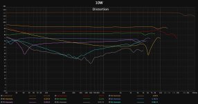
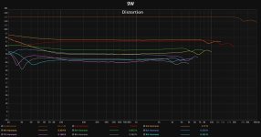
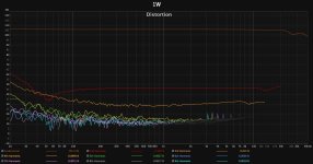
The second loop is more “global” I guess as it wraps around the FET as well as the el34. This was also adjusted to meet my linearly and output Z goals. I do try and leave some elements of my designs outside a feedback loop and in this case it’s the first stage. In regards to the loop loading that stage, the distortion at that point is consistently very low and the majority of the distortion of this amp is generated in the output stage after transitioning to A2. Did you have a look at my detailed distortion sweeps? I’ll be doing measurements on the finished amp soon and post them. I’ll be testing all frequencies at all powers for distortion and linearity so it should be very telling.
Many of your other suggestions are very interesting but they sound like a different amp than I set out to create in this case.
In regards to the implication that A2 will destroy my el34s I don’t know what the future holds but I can say that in testing I have abused the output stage badly. Running it in A2 for extended periods. Now that the amp is built the A2 indicator LED only occasionally flickers when it’s absolutely cranked. At least in my system. All that to say, I think in typical music listening situations the G1 current will be small compared to the testing. That said I do expect the 100% dissipation operation point I’m using to shorten tube life.
Sorry if I didn’t respond to every point you made. I appreciate your thoughtful comment.
My goal with amp design is my own entertainment. So that might explain some of my design choices 😂.
Of course a P channel device on the cathode was considered but I thought it would be more fun and less typical to run a cascode output stage. Also it’s nice not to need a negative rail.
Several types of feedback were tried during the design phase on my breadboard, including a global loop. In general I’m only looking for the feedback loop to have high stability and a good return on investment in regards to gain vs output Z. I’m also looking at frequency response, wanting to make sure the output stage can react to the non infinite output transformer inductance.
Placing the output transformer secondary in series with the cathode mosfet was also considered as this would eliminate a cap. Though I decided against it because I wanted to be able to fine tune the amount of feedback and didn’t want dc on the output if I could help it.
The second loop is more “global” I guess as it wraps around the FET as well as the el34. This was also adjusted to meet my linearly and output Z goals. I do try and leave some elements of my designs outside a feedback loop and in this case it’s the first stage. In regards to the loop loading that stage, the distortion at that point is consistently very low and the majority of the distortion of this amp is generated in the output stage after transitioning to A2. Did you have a look at my detailed distortion sweeps? I’ll be doing measurements on the finished amp soon and post them. I’ll be testing all frequencies at all powers for distortion and linearity so it should be very telling.
Many of your other suggestions are very interesting but they sound like a different amp than I set out to create in this case.
In regards to the implication that A2 will destroy my el34s I don’t know what the future holds but I can say that in testing I have abused the output stage badly. Running it in A2 for extended periods. Now that the amp is built the A2 indicator LED only occasionally flickers when it’s absolutely cranked. At least in my system. All that to say, I think in typical music listening situations the G1 current will be small compared to the testing. That said I do expect the 100% dissipation operation point I’m using to shorten tube life.
Sorry if I didn’t respond to every point you made. I appreciate your thoughtful comment.
Hi, out of interest, is the link for one transformer or a pair of transformers? It seems a good price for a pair.suitable for EI34 KT88 FU7 FU50 6P3P, inductance 41H
https://a.aliexpress.com/_mPTPstu
Thank you
- Home
- Amplifiers
- Tubes / Valves
- EL34 A2 Cascode SE triode