You are using an out of date browser. It may not display this or other websites correctly.
You should upgrade or use an alternative browser.
You should upgrade or use an alternative browser.
Heretic Loudspeaker A612 Clone
- Thread starter dualuxe
- Start date
In answer to A1008, I posted data to help others approach the original design, and at the same time I wanted to try and understand serial Xovers a bit more as I had never tried the idea before.
I am slowly building a box of approx. 80 litres along the shape of an old Tannoy Chatsworth sized cabinet and now have a different serial over i want to try and tune further once i have built the cabinet.
I imagine that Chris's post 82 would work as one of many possible solutions.
I am slowly building a box of approx. 80 litres along the shape of an old Tannoy Chatsworth sized cabinet and now have a different serial over i want to try and tune further once i have built the cabinet.
I imagine that Chris's post 82 would work as one of many possible solutions.
I think ? it looks more like this, without the resistor across the tweeter.
L-Pad on Series Crossover?
https://www.diyaudio.com/community/threads/l-pad-on-series-crossover.397411/
post# 5 AllenB

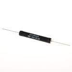
1.8 ohm x2 parallel = .9 ohms
https://www.solen.ca/en/products/so...-resistors-aoc1600g1r8-1_8ohm-16watt-resistor
L-Pad on Series Crossover?
https://www.diyaudio.com/community/threads/l-pad-on-series-crossover.397411/
post# 5 AllenB
1.8 ohm x2 parallel = .9 ohms
https://www.solen.ca/en/products/so...-resistors-aoc1600g1r8-1_8ohm-16watt-resistor
Attachments
Last edited:
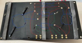
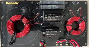
This looks to be correct. from post #66.Is this it as traced out by our friend?

Count on the back: Left side bottom to top 1-6 ( #1-8.2uf, #2 -1.6 mH,#3-10 uf,#4-1.6mH,#5 Res,#6-Res.)
Right Side 7-12 top to bottom (#7-Res,#8-Res,#9-.62mH,#10-.62mH,#11-10uF,#12-8.2uf
post#71
The smaler coils Solen 20.62 ( 0,62mH )and 201.6 (1,6mH ) both 20awg or 0,8mm Pure Copper Solid Round Type.
The bigger types, maybe 16awg.?????
Attachments
Last edited:
Just a thought regarding PCB images?
Look at component side image big inductor on LHS.
Now look at posted images of the underside, ie the soldered side. Note that the solder input terminals are not flipped they still align?
Question: shouldn't the larger L1 inductor be on the RHS now?
I am in the garage attempting cutting wood for cabinets today, so the cold may have addled my brain.
I was wondering about that, looks like he flipped the image so we could trace it easier.
If you look at the component side the tweeter terminals are on the bottom right. Amp +/- near the mounting hole.
The tweeter terminals are on the bottom right- flipped image.
The Zap straps Larger Coil on the left, Smaller Coil on the right.
Normal back & top pcb.


Flipped pcb image

from post #88 Try this & apply to the crossover on post #27 or #66
Backside flipped (image supplied), count on the back: Left side bottom to top components 1-6 ( #1-8.2uf, #2 -1.6 mH,#3-10 uf,#4-1.6mH,#5 Res,#6-Res.)
Right Side 7-12 top to bottom (#7-Res,#8-Res,#9-.62mH,#10-.62mH,#11-10uF,#12-8.2uf
Woofer - negative see post #65

If you look at the component side the tweeter terminals are on the bottom right. Amp +/- near the mounting hole.
The tweeter terminals are on the bottom right- flipped image.
The Zap straps Larger Coil on the left, Smaller Coil on the right.
Normal back & top pcb.
Flipped pcb image
from post #88 Try this & apply to the crossover on post #27 or #66
Backside flipped (image supplied), count on the back: Left side bottom to top components 1-6 ( #1-8.2uf, #2 -1.6 mH,#3-10 uf,#4-1.6mH,#5 Res,#6-Res.)
Right Side 7-12 top to bottom (#7-Res,#8-Res,#9-.62mH,#10-.62mH,#11-10uF,#12-8.2uf
Woofer - negative see post #65
Last edited:
A1008, thanks for taking the time to get these photos of the crossover. Much appreciated!Well, then I just go back and enjoy my AD612 and leave you guys to it. Good luck with your work and have fun.
The smaler coils Solen 20.62 ( 0,62mH )and 201.6 (1,6mH ) both 20awg or 0,8mm Pure Copper Solid Round Type.
The bigger types, maybe 16awg.?????
Yes- Thank You, A1008 without your help this would not be solved!
POST # 89 Crossover
https://solen.ca/en/categories/inductors/products
Solen std 1.6mH diameter dcr- ohms
S201.6 20g 57mm .96
S181.6 18g 64mm .63
S161.6 16g 76mm .44
S141.6 14g 89mm .29
S121.6 12g 102mm .2
Mundorf vs Solen
post #70
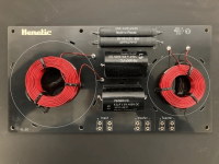
Same pcb board. Any idea$s.
from post #1 White Mundorf Cap EVO aluminium Oil 450VDC Caps , the coils fill the board
$30 usd Mundorf Cap 10 ufd
https://partsconnexion.com/collections/mundorf-evo-aluminum-oil-film-capacitors/products/mundorf-capacitor-10uf-450vdc-mcap®-evo-oil
View attachment 1276412
from post #11 Solen PB-MKP-FC 400 VDC Caps, the coils don't fill the board.
$6.55 usd Solen Cap 10 ufd
https://partsconnexion.com/products...-400vdc-pb-series?_pos=8&_sid=6d8df40b7&_ss=r
View attachment 1276413
Last edited:
A1008, could you post the dimensions of the front port on your AD612? Thanks!Well, then I just go back and enjoy my AD612
If you don’t want a significant peak in the midrange where the impedance skyrockets you don’t want to use a high output impedance amplifier.
The box size would also need the output impedance added to the Qt when simulating the box.
dave