IR2117 high side driver expanation
Well, Dan, yes, you are missing something. Just visit the International Rectifier site, "www.irf.com", and open the data sheet for the IR2117, IR2127-2128, IR2110, etc. The circuit is quite straightforward. The bootstrap diode charges the bootstrap capacitor from the input supply. The lower side of the boot cap is at the n-channel MOSFET's source terminal, which is near ground during the FET OFF time. The other cap terminal is one diode drop below the input rail. The cap is charged to roughly the input rail voltage, or 13.5 volts in the automobile case. When the FET is switched on, the upper side of the boot cap is connected to the FET gate, the FET turns ON since 13.5 volts is across its gate and source pins, and the source gets yanked up to very near the drain voltage, which is connected to the input rail. Since the bootstrap cap is connected across the FET's gate and source, it holds the 13.5 volts, because the bootstrap diode is now reverse biased, and is effectively out of the circuit. If the input rail is 13.5 volts, which is feeding the N-MOSFET's drain, and the source is 0.5 volt below the drain, then the source is at 13.0 volts. The cap is charged to 13.5 volts, one end is at the source, or 13.0 volts, while the other end is at the gate, 13.5 volts higher, or 26.5 volts. Hence, the gate drive voltage is 26.5 minus 13.5, or 13.0 volts above the rail. The bootstrap diode and capacitor generate an elevated gate drive voltage without the need for an additional power supply. This is a well established practice. I've been doing this since the '80's. I hope this clears things up regarding high side gate drive. Best regards.
So this chip generates the voltage to drive the FET gate from thin air? Seems to me you'd still need 10 to 20 volts above your supply rail to make it work. Which means a second voltage source -> and more parts. (Unless I'm missing something)
Well, Dan, yes, you are missing something. Just visit the International Rectifier site, "www.irf.com", and open the data sheet for the IR2117, IR2127-2128, IR2110, etc. The circuit is quite straightforward. The bootstrap diode charges the bootstrap capacitor from the input supply. The lower side of the boot cap is at the n-channel MOSFET's source terminal, which is near ground during the FET OFF time. The other cap terminal is one diode drop below the input rail. The cap is charged to roughly the input rail voltage, or 13.5 volts in the automobile case. When the FET is switched on, the upper side of the boot cap is connected to the FET gate, the FET turns ON since 13.5 volts is across its gate and source pins, and the source gets yanked up to very near the drain voltage, which is connected to the input rail. Since the bootstrap cap is connected across the FET's gate and source, it holds the 13.5 volts, because the bootstrap diode is now reverse biased, and is effectively out of the circuit. If the input rail is 13.5 volts, which is feeding the N-MOSFET's drain, and the source is 0.5 volt below the drain, then the source is at 13.0 volts. The cap is charged to 13.5 volts, one end is at the source, or 13.0 volts, while the other end is at the gate, 13.5 volts higher, or 26.5 volts. Hence, the gate drive voltage is 26.5 minus 13.5, or 13.0 volts above the rail. The bootstrap diode and capacitor generate an elevated gate drive voltage without the need for an additional power supply. This is a well established practice. I've been doing this since the '80's. I hope this clears things up regarding high side gate drive. Best regards.
Claude, as Linear Tech states, however
in one of their mirthful application notes (the only company with humor in their ap-notes) Linear Tech states that being an SMPS designer will drive you to insanity.
at least it's Hallo'ween tomorrow and all the analog filter designers will be in full regalia.
in one of their mirthful application notes (the only company with humor in their ap-notes) Linear Tech states that being an SMPS designer will drive you to insanity.
at least it's Hallo'ween tomorrow and all the analog filter designers will be in full regalia.
Re: Claude, as Linear Tech states, however
I've glanced at the datasheets several times, and they don't explain the bootstrap operation at all. I finally found it in an application note, buried somewhere on their site.
Ok, I now understand now the chips work. Very dissapointed that isn't spelled out in their datasheets! They do make full bridge more appealing...
However, I've still never seen a bridge on the 12 volt side of any audio amps. I've looked very closely at several 1000W/Ch Digitals, and even measured their output. My first instinct is to assume that you can do it with less parts, and more cost effeciently with push-pull... ...as evidenced by the fact car audio suppliers don't do full bridge.
Ah, Yes, but insanity is half the fun!
Claude Abraham said:The bootstrap diode charges the bootstrap capacitor from the input supply...
... I hope this clears things up regarding high side gate drive. Best regards.
I've glanced at the datasheets several times, and they don't explain the bootstrap operation at all. I finally found it in an application note, buried somewhere on their site.
Ok, I now understand now the chips work. Very dissapointed that isn't spelled out in their datasheets! They do make full bridge more appealing...
However, I've still never seen a bridge on the 12 volt side of any audio amps. I've looked very closely at several 1000W/Ch Digitals, and even measured their output. My first instinct is to assume that you can do it with less parts, and more cost effeciently with push-pull... ...as evidenced by the fact car audio suppliers don't do full bridge.
jackinnj said:in one of their mirthful application notes (the only company with humor in their ap-notes) Linear Tech states that being an SMPS designer will drive you to insanity.
Ah, Yes, but insanity is half the fun!
full bridge, half, push-pull, whatever!
This full bridge topology seems to be a source of controversy. I don't want to dwell on this any more. Let me just summarize and let the chips fall where they may. Which topology works best and is cost-effective as well as space-effective, power-efficient, lowest noise, etc. varies from one case to the next.
As far as first instincts and assumptions go, it's been well known for decades that the push-pull costs less than the full bridge, and requires fewer parts. Neither I nor anyone here has implied otherwise. My issue was with a couple of posters who went as far as saying that push-pull and/or half bridge topologies were actually better than full bridge, regarding efficiency, since a full bridge incurs two MOSFET voltage drops per switch cycle, vs. only one for the other two circuits. This is plain false, and I had to address it. As far as the best choice for a particular application goes, it's debatable since cost, space, weight, efficiency, noise, and short circuit protection all factor in, and the user may have a stronger need for some of these parameters, and is willing to sacrifice others. My goal was only to make readers aware of the available options, and the pros and cons of each topology, not to persuade or dissuade them from any of them. There are however some hard facts which are not debateable. Here goes some of them.
The simplest SMPS is a non-isolated, or transformerless dc to dc converter. Circuit topologies include buck, boost, buck-boost (inverting & non-inverting), & SEPIC. They are popular when no isolation is needed. If the input source is the ac power line, isolation is needed per safety agency requirements (UL, CSA, VDE, etc.). A transformer is needed in these cases. The transformer topologies are from simple to most complex are as follows:
flyback, forward, push-pull, half bridge, full bridge.
The flyback is the simplest, offers the fewest parts count, lowest cost, and easily provides multiple outputs via multiple secondaries with good cross-regulation. It places the highest stress on the parts and is good for 75 to 200 watts depending on voltage & current requirements. It is the noisiest of the 5 circuits. It requires more frequency compensation for stability, and has relatively sluggish transient response. It requires one MOSFET, one rectifier, & single primary / single secondary transformer
The forward is a step up from the flyback. It is a little more complex, costing more. It places less stress on the parts, is easier to stabilize than the flyback, has lower noise, and quicker transient response. It is recommended to around 200 watts. It requires one MOSFET, two rectifiers, one inductor, & single primary / single secondary transformer
The push-pull surpasses the forward in all respects as far as performance goes. The interleaved two phase operation reduces noise, reduces part stress, and improves efficiency. It is more complex than forward, costing more. The flyback and forward can use either voltage-mode or current-mode control, but the push-pull should only be used with current-mode control since any volt-second unbalance in the primary could cause flux walking and saturation results (with voltage-mode, a series cap can protect against saturation). It is recommended from around 200 to 500 watts. The two MOSFETs must withstand twice the input supply voltage, and one times the load current (referred to primary). It requires two MOSFETs, both low-side driven, two rectifiers, one inductor, & a center-tapped primary / center-tapped secondary xfmr.
The half bridge surpasses the flyback and forward, and in some cases is a better choice than the push-pull. It differs from the push-pull as follows. The two MOSFETs must withstand one times the input supply voltage, but twice the load current (ref to primary). It is more prone to saturation due to two sources of unbalance, unbalanced volt-seconds, and charge unbalance in the capacitive half bridge network. A series cap is recommended to prevent saturation, even with current-mode control. For high voltage, low current requirements, I'd use a half bridge instead of a push-pull. Otherwise, I prefer the push-pull. It requires two MOSFETs, one high-side driven, one low-side driven, two rectifiers, three capacitors (substantial), one inductor, & a simple primary / center-tapped secondary xfmr. It is recommended to 500 watts.
Last, is the full bridge, the premium topology, to be used when the highest power is needed, & the expense can be justified. It is the most complex, requires the most parts, & takes up the most space & weight. It places the lowest stress on each part. The four FETs must withstand only one times the input supply voltage, and one times the load current (ref to primary). It offers the highest efficiency. As with push-pull & half bridge, current-mode is my preferred control scheme to preserve volt-second balance on primary. It requires four MOSFETs, two high-side driven, two low-side driven, two rectifiers, one inductor, & a simple primary / center-tapped secondary xfmr. It is recommended from 500 watts & higher
I hope I've shed some light on the various options available. As we can see, the more you demand in terms of performance, the more you have to pay. As the old saying goes, "Mother Nature will gladly trade with us, but she doesn't give anything away for free".
Lastly, I'm a bit perplexed about the "1000 W / channel amp". That's 2000 watts! At the car voltage of 13.5 volts, the input current is near 150 amps (assuming 100% efficiency)!! Alternators only put out 150 amps, the largest I've known of rates at 200 amps. That doesn't leave much for the rest of the car. Best regards to all.
"However, I've still never seen a bridge on the 12 volt side of any audio amps. I've looked very closely at several 1000W/Ch Digitals, and even measured their output. My first instinct is to assume that you can do it with less parts, and more cost effeciently with push-pull... ...as evidenced by the fact car audio suppliers don't do full bridge. "
This full bridge topology seems to be a source of controversy. I don't want to dwell on this any more. Let me just summarize and let the chips fall where they may. Which topology works best and is cost-effective as well as space-effective, power-efficient, lowest noise, etc. varies from one case to the next.
As far as first instincts and assumptions go, it's been well known for decades that the push-pull costs less than the full bridge, and requires fewer parts. Neither I nor anyone here has implied otherwise. My issue was with a couple of posters who went as far as saying that push-pull and/or half bridge topologies were actually better than full bridge, regarding efficiency, since a full bridge incurs two MOSFET voltage drops per switch cycle, vs. only one for the other two circuits. This is plain false, and I had to address it. As far as the best choice for a particular application goes, it's debatable since cost, space, weight, efficiency, noise, and short circuit protection all factor in, and the user may have a stronger need for some of these parameters, and is willing to sacrifice others. My goal was only to make readers aware of the available options, and the pros and cons of each topology, not to persuade or dissuade them from any of them. There are however some hard facts which are not debateable. Here goes some of them.
The simplest SMPS is a non-isolated, or transformerless dc to dc converter. Circuit topologies include buck, boost, buck-boost (inverting & non-inverting), & SEPIC. They are popular when no isolation is needed. If the input source is the ac power line, isolation is needed per safety agency requirements (UL, CSA, VDE, etc.). A transformer is needed in these cases. The transformer topologies are from simple to most complex are as follows:
flyback, forward, push-pull, half bridge, full bridge.
The flyback is the simplest, offers the fewest parts count, lowest cost, and easily provides multiple outputs via multiple secondaries with good cross-regulation. It places the highest stress on the parts and is good for 75 to 200 watts depending on voltage & current requirements. It is the noisiest of the 5 circuits. It requires more frequency compensation for stability, and has relatively sluggish transient response. It requires one MOSFET, one rectifier, & single primary / single secondary transformer
The forward is a step up from the flyback. It is a little more complex, costing more. It places less stress on the parts, is easier to stabilize than the flyback, has lower noise, and quicker transient response. It is recommended to around 200 watts. It requires one MOSFET, two rectifiers, one inductor, & single primary / single secondary transformer
The push-pull surpasses the forward in all respects as far as performance goes. The interleaved two phase operation reduces noise, reduces part stress, and improves efficiency. It is more complex than forward, costing more. The flyback and forward can use either voltage-mode or current-mode control, but the push-pull should only be used with current-mode control since any volt-second unbalance in the primary could cause flux walking and saturation results (with voltage-mode, a series cap can protect against saturation). It is recommended from around 200 to 500 watts. The two MOSFETs must withstand twice the input supply voltage, and one times the load current (referred to primary). It requires two MOSFETs, both low-side driven, two rectifiers, one inductor, & a center-tapped primary / center-tapped secondary xfmr.
The half bridge surpasses the flyback and forward, and in some cases is a better choice than the push-pull. It differs from the push-pull as follows. The two MOSFETs must withstand one times the input supply voltage, but twice the load current (ref to primary). It is more prone to saturation due to two sources of unbalance, unbalanced volt-seconds, and charge unbalance in the capacitive half bridge network. A series cap is recommended to prevent saturation, even with current-mode control. For high voltage, low current requirements, I'd use a half bridge instead of a push-pull. Otherwise, I prefer the push-pull. It requires two MOSFETs, one high-side driven, one low-side driven, two rectifiers, three capacitors (substantial), one inductor, & a simple primary / center-tapped secondary xfmr. It is recommended to 500 watts.
Last, is the full bridge, the premium topology, to be used when the highest power is needed, & the expense can be justified. It is the most complex, requires the most parts, & takes up the most space & weight. It places the lowest stress on each part. The four FETs must withstand only one times the input supply voltage, and one times the load current (ref to primary). It offers the highest efficiency. As with push-pull & half bridge, current-mode is my preferred control scheme to preserve volt-second balance on primary. It requires four MOSFETs, two high-side driven, two low-side driven, two rectifiers, one inductor, & a simple primary / center-tapped secondary xfmr. It is recommended from 500 watts & higher
I hope I've shed some light on the various options available. As we can see, the more you demand in terms of performance, the more you have to pay. As the old saying goes, "Mother Nature will gladly trade with us, but she doesn't give anything away for free".
Lastly, I'm a bit perplexed about the "1000 W / channel amp". That's 2000 watts! At the car voltage of 13.5 volts, the input current is near 150 amps (assuming 100% efficiency)!! Alternators only put out 150 amps, the largest I've known of rates at 200 amps. That doesn't leave much for the rest of the car. Best regards to all.
Thanks for that Claude, i was originally going to go push-pull, because i didn't realise the advantages of the other formats, but as you've very well put, there is some definite merit in them.
I might boost this amp up a tad more in power and make it full bridge, just for the experience of building it.
Re the stupidly high powered amps, yeah they exist, yes they pull over 100 amps. You watch a high powered system and the whole car dims on the beat, unless they use very large 12v capacitance to smooth it out.
I've been at car shows where they had in car lcds, the backlights on them turned off on the beat, due to the voltage drop.
Re: full bridge, half, push-pull, whatever!
Claude,
Have not had a chance to read your whole post completely. Will do so ASAP.
However...
Yeah, 150+ Amps, Easy. Maybe even 200 Amps or more.
Put a scope on the 12 volt input, and a volt meter. The meter will read the average the voltage at the terminals (Often 11 volts). However closer inspection with the scope will reveal voltages as low as 9 volts during conduction cycles of the power switches.
In short, the supply will often need to get it's 2kW from 9 volts, not 13.5. (I wish I had some scope images of traces showing this. I will try to save some to disk the next time I get a chance. )
-Dan
P.S. This reminds me... ...FYI for anyone building a high power SMPS supply for car audio. Assume the terminal voltage will be lower than 13.8 volts, Much lower...
Claude Abraham said:Lastly, I'm a bit perplexed about the "1000 W / channel amp". That's 2000 watts! At the car voltage of 13.5 volts, the input current is near 150 amps (assuming 100% efficiency)!! Alternators only put out 150 amps, the largest I've known of rates at 200 amps. That doesn't leave much for the rest of the car.
Claude,
Have not had a chance to read your whole post completely. Will do so ASAP.
However...
Yeah, 150+ Amps, Easy. Maybe even 200 Amps or more.
Put a scope on the 12 volt input, and a volt meter. The meter will read the average the voltage at the terminals (Often 11 volts). However closer inspection with the scope will reveal voltages as low as 9 volts during conduction cycles of the power switches.
In short, the supply will often need to get it's 2kW from 9 volts, not 13.5. (I wish I had some scope images of traces showing this. I will try to save some to disk the next time I get a chance. )
-Dan
P.S. This reminds me... ...FYI for anyone building a high power SMPS supply for car audio. Assume the terminal voltage will be lower than 13.8 volts, Much lower...
For low voltages [lets say peak voltages less than 100V] I think that push-pull and MOSFETs have serious advantages because :
- Doubling the number of switching devices is more expensive than using two symmetric primary windings instead of one since a 60V device usually cost less than two 30V devices triying to match half the Rds-on of the 60V device
- Using twice the number of switching devices uses much more board and heatsink space than using two symmetric primary windings
- A 60V device usually has less than double the Rds-on of a 30V device of similar current and trying to match half the price
- 60V devices are available from zillions of manufacturers and easier to buy since they are the most commonly used, this also makes it easy to get them cheaper
Also, synchronous rectification is very useful for low voltages [<100V peak] since in this domain MOSFETs have lower conduction losses and cand handle lots more current per device than diodes [even schotky] allowing to save space, heat and money
MOSFETs loss their attractive for voltages higher than 100V as their switching losses raise with the square of the blocking Vds rating [or something like that]
Bipolars and IGBTs also have conduction losses rising with the Vce blocking rating but this is slower than a square law so for, lets say 200V or more, Bipolars and IGBTs allways have lower conduction losses than MOSFETs of simiar current and also tend to be cheaper
Since conduction losses increase with increased blocking capability, for high voltages half bridge, full bridge, bipolars and IGBTs have advantages, and push-pull and MOSFETs have disadvantages
At high voltages you usually have a transformer with lots of turns in the primary using lots of space and making it hard to double it to make two symmetric primares, at low voltages it's lots easier to double it since primaries can be as low as 4 or 6 turns
Also, at high voltages inter-turn and inter-winding capacitance, and the blocking capability of the insulation of wire used have to be taken into account making it hard to use a symmetric primary winding without more ringing, more leakage inductance or broken insulation problems betweem turns of different windings
At low voltages you can afford to double the blocking capability of the switching devices without increasing conduction losses, in fact, you may get lower losses than stacking two devices
At high voltages doubling the blocking capability of the devices has a large impact on conduction losses and sometimes on switching speed so common sense dictates the use of half-bridge for low-cost/low/medium power and full-bridge for high power
Also, at high voltages synchronous rectification losses its attractive since diodes tend to be faster and have lower conduction losses than switching devices
One of projects I'm working on is a compact 160-250V AC to 0-15V DC and 2-4KW converter, its purpose is to power and test Car-Audio systems
The mains is rectified with apparent 'resistive load' trough a typical PFC section based in a boost converter and a L4981A control IC [from SGS-Thomson] to get 450V DC pseudo-regulated as output
Then, I use a buck section for regulation but it has a transformer-coupling in the middle so the inductor feeds the primary side of the transformer [driven by a full bridge] and the secondary side of the transformer feeds the filter capacitrs [the output, it has push-pull synchronous rectification]
The use of the transformer-coupling also made very easy to operate this loop in current mode and implement pulse-by-pulse current limiting since it's easy to place a little current sense transformer in series with main transformer
The PFC and te buck operate at 95Khz, the transformer operates at 47,5Khz but I'm planning to speed up the transformer as the switching losses I'm geting in the full bridge are much lower than te ones found in the rest of the circuit since it's being feed from an inductor and I'm using zero current turn on [it's easy to implement]
For 450V switching I've tried MOSFETs [IRFP460 from IR and SGS-Thomson] and IGBTs [SGP10N60 from Infineon/Siemens]
I prefer by far IGBTs, at these frequencies they show slighty higher switching losses but lower conduction losses [similar total losses], much less ringing and RFI due to lower output capacitance and ease of drive due to very low input and reverse-transfer capacitances
Further, those IGBTs are rated at 600V 19A at 25ºC vesus 500V 20A for the MOSFETs, have TO-220 casing versus TO-247 and are much cheaper, I think there is no reason to use MOSFETs for less than 150Khz and more than 200V applications
As a transformer, a toroid core of 36mm OD, 23mm ID and 15mm height [ferroxcube 3E-25 material since I can't get anything better in my country] showed to be rignt up to 1Kw, I've tested it up to 2Kw but leakage inductance resetting starts to steal 10% or more of time [at 47,5 Khz I'm using 4 volts per turn]
To drive the full bridge, the buck and the syncronous rectification I use two pulse transformers, a SG3525 IC and some CMOS gates
I hope to get it finished and reliable some day...
Eva said:-them cheaper
Then, I use a buck section for regulation but it has a transformer-coupling in the middle so the inductor feeds the primary side of the transformer [driven by a full bridge] and the secondary side of the transformer feeds the filter capacitrs [the output, it has push-pull synchronous rectification]
For 450V switching I've tried MOSFETs [IRFP460 from IR and SGS-Thomson] and IGBTs [SGP10N60 from Infineon/Siemens]
I prefer by far IGBTs, at these frequencies they show slighty higher switching losses but lower conduction losses [similar total losses], much less ringing and RFI due to lower output capacitance and ease of drive due to very low input and reverse-transfer capacitances
Further, those IGBTs are rated at 600V 19A at 25ºC vesus 500V 20A for the MOSFETs, have TO-220 casing versus TO-247 and are much cheaper, I think there is no reason to use MOSFETs for less than 150Khz and more than 200V applications
Here are some alternate possibilities. For secondary rectification using high current Schottky diodes may make things easier. I have had good sucess paralleling diodes despite the common notion that it is poor practice. The reason it works is that so long as they all are the same device and all are in the same ambient environment, they share current rather evenly. After all, they do experience rising voltage drop with increasing current, which far outweighs the negative temperature coefficient of the voltage drop. Even if you figure on derating each diode to 3/4 of its current rating, it still turns out to give a big current capability increase.
Instead of the IRFP460 mosfet, consider using a later generation type. For instance, what about an IRFBA90N20D? Its channel resistance is way less than that of the 460 though the gate capacitance is higher. Besides, mosfets are more reliable than IGBT's.
Those are just some thoughts. Thanks for yours.
I've ben taking a look at the 500V and 600V devices now available from IRF
In 500V and about 20A devices max. Rds-on has dropped from about 0,27 ohms to about 0,24 ohms, so not much improvement there
In 600V devices I took IRFB17N60K and compared it to SKP10N60, the ones I use ['SGP' does not include reverse diode and 'SKP' includes a fast recovery one]
- Both devices come into TO-220 Package
- Both devices are rated at about 11A at 100ºC
- IGBT has 2V Vce-sat typ. for Vge=10V/10A/25ºC and MOSFET has 3.4V Vds-on typ in same conditions so conduction losses are 70% higher
- IGBT has about 500pF input capacitance at Vge=10V and MOSFET has about 3nF in same conditions
- IGBT has about 70pF output capacitance at Vce=25V and MOSFET has about 240pF in same conditions
- IGBT has about 50pf reverse transfer capacitance at Vcg=25V and MOSFET has about 20pF
I have to admit that MOSFETs have improved a lot since IRFP460 that had 2.4V drop typ for 10V/12A/25ºC, 4,2nF input capacitance, 870pF output capacitance and 350pF reverse transfer capacitance
With so high capacitances I had lots of ringing at turn-off [so lots of RFI generated] and needed about 2A gate current to be able to turn off the device fast enough to keep reasonable switching losses 'fighting' with the reverse transfer capacitance that slowed down turn-off a lot
Then IGBTs came as a magic solution to all these problems
Capacitances found in modern 500V and 600V MOSFETs tend to be more manageable and conduction losses tend to be more reasonable but the price of these devices is 2..3..4 times higher [at least in my country] than the price of equivalent IGBTs with less conduction losses and very easy to drive
Of course, the 200V 94A device you mentioned has outstanding specifications but as I have said, MOSFETs loss their attactive gradually as required Vds blocking capability increases [take a look at 1200V MOSFETs versus 1200V IGBTs for industrial use]
Respect to diodes, as you said, paralelling devices works great for high currents as the dominant voltage drop comes from the resistive portion of the diode so it's like if there were current sharing resistors in series with each diode
But with modern 40-60V MOSFETs I get 40-60A from only one device in TO-220 casing, in comparison, Schottky diodes in TO-220 case tend to be rated at no more than 20A so you need more devices, more cases, more space and each diode tends to cost the same as or a bit less than a 40-60V MOSFET so rectifying with diodes is right, very simple but more expensive
At very high currents, by paralelling the right amount of diodes, you can get the same or lower voltage drop`than with MOSFETs but at lower currents MOSFETs outperform Schottkys due to its fully resistive behavior versus quasi-constant voltage drop plus resistive component for the Schottky
In general I like anything capable of providing cost & space saving [since I'm not rich!], lower dissipation is also welcome")
In 500V and about 20A devices max. Rds-on has dropped from about 0,27 ohms to about 0,24 ohms, so not much improvement there
In 600V devices I took IRFB17N60K and compared it to SKP10N60, the ones I use ['SGP' does not include reverse diode and 'SKP' includes a fast recovery one]
- Both devices come into TO-220 Package
- Both devices are rated at about 11A at 100ºC
- IGBT has 2V Vce-sat typ. for Vge=10V/10A/25ºC and MOSFET has 3.4V Vds-on typ in same conditions so conduction losses are 70% higher
- IGBT has about 500pF input capacitance at Vge=10V and MOSFET has about 3nF in same conditions
- IGBT has about 70pF output capacitance at Vce=25V and MOSFET has about 240pF in same conditions
- IGBT has about 50pf reverse transfer capacitance at Vcg=25V and MOSFET has about 20pF
I have to admit that MOSFETs have improved a lot since IRFP460 that had 2.4V drop typ for 10V/12A/25ºC, 4,2nF input capacitance, 870pF output capacitance and 350pF reverse transfer capacitance
With so high capacitances I had lots of ringing at turn-off [so lots of RFI generated] and needed about 2A gate current to be able to turn off the device fast enough to keep reasonable switching losses 'fighting' with the reverse transfer capacitance that slowed down turn-off a lot
Then IGBTs came as a magic solution to all these problems
Capacitances found in modern 500V and 600V MOSFETs tend to be more manageable and conduction losses tend to be more reasonable but the price of these devices is 2..3..4 times higher [at least in my country] than the price of equivalent IGBTs with less conduction losses and very easy to drive
Of course, the 200V 94A device you mentioned has outstanding specifications but as I have said, MOSFETs loss their attactive gradually as required Vds blocking capability increases [take a look at 1200V MOSFETs versus 1200V IGBTs for industrial use]
Respect to diodes, as you said, paralelling devices works great for high currents as the dominant voltage drop comes from the resistive portion of the diode so it's like if there were current sharing resistors in series with each diode
But with modern 40-60V MOSFETs I get 40-60A from only one device in TO-220 casing, in comparison, Schottky diodes in TO-220 case tend to be rated at no more than 20A so you need more devices, more cases, more space and each diode tends to cost the same as or a bit less than a 40-60V MOSFET so rectifying with diodes is right, very simple but more expensive
At very high currents, by paralelling the right amount of diodes, you can get the same or lower voltage drop`than with MOSFETs but at lower currents MOSFETs outperform Schottkys due to its fully resistive behavior versus quasi-constant voltage drop plus resistive component for the Schottky
In general I like anything capable of providing cost & space saving [since I'm not rich!], lower dissipation is also welcome
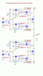
Hi davesaudio, here is a link to a circuit which I came up with in the past. The values of R1,R2,R3, and R4 should be adjusted for optimal performance.
http://f6.grp.yahoofs.com/v1/gJO7P2...zm0NDRcFDLO1oDMNUQP2/proposedhighpowerout.gif
I can't think of any universal high side drivers off of the top of my head. But some lower voltage ones are out there.
http://f6.grp.yahoofs.com/v1/gJO7P2...zm0NDRcFDLO1oDMNUQP2/proposedhighpowerout.gif
I can't think of any universal high side drivers off of the top of my head. But some lower voltage ones are out there.
davesaudio said:linky no worky?
should I rephrase " high side driver circuit using discrete components to drive the gate of the switching device beyond the rails?"
well something like that anyways...
Sorry, try copying and then pasting the link into the browser window.
The circuit is a such as you seek, and it can charge and discharge high capacitance gates, or I should say, it is designed that way. I have not actually built and tested it.
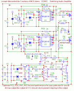
davesaudio, there is a lower power high-side driver in the circuit in this class D amp which I actually tested as a real circuit.
http://f5.grp.yahoofs.com/v1/8PW7P-...h7GnHQko1oVfNGVl5OEFyM1D/100 watt class D.gif
http://f5.grp.yahoofs.com/v1/8PW7P-...h7GnHQko1oVfNGVl5OEFyM1D/100 watt class D.gif
- Status
- This old topic is closed. If you want to reopen this topic, contact a moderator using the "Report Post" button.
- Home
- General Interest
- Car Audio
- Higher power switching psu, any design advice?