• Member Blogs have been stealth lauched / soft launched. Members who are keen to start a useful informative blog and who will keep it current can contact GerardV to be set up. Blogs that go stale will be archived.

Ideas for the Next - a microphone preamp

Somewhat of an idle thought, but it's been in the back of my mind for a while and since I'll be soon taking ownership of an Audio Technica 4047/SV it's an opportunity to see what can be done on the signal amplification side vs. what I have now, a Tascam DR-60D Mk II.

Nothing fancy planned, just a low-noise, high-gain, linear analog preamplifier. One channel. The complication is I need phantom power, and that means a balanced or at least pseudo-balanced front end.

Background reading and general research in progress:

https://www.radioworld.com/tech-and-gear/that-thing-a-solid-state-mic-preamp-project

https://sound-au.com/articles/p-48.htm
 

rjm

Member
Joined 2004
Paid Member
ThatMicPre project with the THAT1510, a fully developed project here on diyaudio.

As commercial products, there's a few that resemble what I had in mind. At the low end, there's the Audio Technica AT-MA2. Midrange there's the
Golden Age Project PRE-73 mk II and PRE-73 DLX mk II, high end there's the BAE 1073DMP. That BAE unit though. Wow. Strongly evocative of the 1960's NASA / Big Science instrumentation aesthetic.

Unfortunately, compared to consumer audio components, there aren't so many online technical manuals, nor, really is there that much in the way of DIY resources either. In the sense that they are both low noise, high gain signal amplifiers, there is a fair bit of commonality with MC phono stages, but considering the details they are quite different. I couldn't just strip the RIAA filter off my Elemerald phono, and 48V phantom power, and call it a day for example. I do, however, plan to reuse as many concepts from that project as I can.

To quickly set out the design goals,

Solid state, two-stage circuit, 48V phantom power, runs off 24 VCT if at all possible. Flat response, low noise - we want to hear the mic, not color it. I'm amenable to a bit of added "character" however. Don't think I need any other features. A balanced output isn't technically necessary but I'd like the design to have that option. No particular limits on size or complexity.
 

rjm

Member
Joined 2004
Paid Member
If we talk about mic preamps, we must discuss the NEVE 1073. For reference, the schematics of this classic, monumental design are attached. (source)

This circuit is so influential that manufacturers are still falling over themselves to offer reproductions and homages. See here, here, and also here.

The short story is that mic preamps need balanced inputs and balanced outputs. In terms of transistor count, this is a lot of work even if in modern designs it's all done in microcircuitry (op amps). The solution, back when op amps were not widely available, was to use transformers on both the input and output. This removes pretty much all the problematic elements of the circuit design, all that's left is to fit a reasonably low noise gain stage between the iron and call it a day.
 

Attachments

  • 1073-fullpak.pdf
    4.9 MB · Views: 86

rjm

Member
Joined 2004
Paid Member
Ideas from Rod Elliot, ESP

Low Noise Microphone Preamplifier
This simple transistor circuit harks back to the Neve 1073. It would typically be interfaced with a mic input transformed and phantom supply.
The thing about these old transistor circuits is that they use electrolytic coupling caps in the audio signal path. A lot of them, since each gain stage is a transistor operating at different bias voltages and operating at relatively high currents/low voltages (low impedance), typically 10 uV caps are needed for DC blocking at the input and output of every stage. So while a canonical sin from an "audiophile" point of view, here you will have to take that coloration on the chin and run with it as part of the "sound".

Low Noise Balanced Microphone Preamp
Transistor differential input stage, coupled to an op amp wired as a differential amplifier. Note the outputs are unbalanced, not balanced.

Even if I were to substitute the Neve-style circuit for something more modern, I'm still leaning on using a mic input transformer. Next post, I'll compile the list of options.
 

rjm

Member
Joined 2004
Paid Member
In the context of line and input audio transformers, there are two things you need to keep track of.

1. The turns ratio of the input and output windings. This defines the change in voltage of the signal passing through the transformer. 1:3.5 turns ratio is 3.5x more voltage on the output. Since the signal power can't change, and P=VI, the output current would be 3.5 times smaller. The more important arrangement of that formula here is P = I^2 R, or R = P / I^2. So, compared to the input "impedance" (the impedance of the source driving the transformer), the output impedance (the impedance seen by the circuit the transformer output is connected to) is (3.5)^2 larger! The input of your following stage must be designed to work well with the (perhaps larger than anticipated) output impedance from the transformer. The more gain you ask from the transformer, the greater the issue this becomes. We'll talk more about that at a later date.

2. The nominal input impedance suggested by the manufacturer. In principle, the source impedance will define the transformer output impedance, and you can connect whatever source to the transformer you like. In practice, one should stick to using sources with impedances relatively close to what the manufacturer intended. This ensures that the transformer is going to behave according to the datasheet specifications. While there's normally no need to match a transformer to a specific microphone, for example, when dealing with the output from a microphone one should use a transformer designed for that application.

All this to say that we can limit our search to transformers specifically advertised as microphone input transformers. In terms of further narrowing down the criteria, we can fix an output impedance based on the noise characteristics of following amplifier circuit we propose to use.

The folks at Jensen explain the details much better than I could, so I'll reproduce it below for reference. The short story is that for BJT input op amps and transistor circuits, choose <5 kohms, for most FET and vacuum tube applications, go with 15k or so.

Transformer selection​

Turns ratio is generally selected for lowest total noise. Lowest noise will come from matching the “optimum source impedance” of the amplifier to the transformer’s “secondary source impedance” – shown in the table above to the right of the colon under “Impedance Ratio.” The optimum source impedance for any amplifier can be calculated by dividing the amplifier’s voltage noise spectral density in V/ √ Hz , such as 1.2 nV/ √ Hz (1.2 nano-volts per root-Hz) by its current noise spectral density in A/ √ Hz , such as 2 pA/ √ Hz (2 pico-amps per root-Hertz). In this example, using figures for the AD797 low-noise op-amp, the answer is 600 Ω, making our JT-16A with its 600 Ω source impedance the best choice. This matching is not critical and mismatches of ±50% generally make less than 1 dB change in total noise. For vacuum tubes, voltage and current noise numbers are difficult to find. However, when they are available, the calculation will generally indicate an optimum source impedance higher than 15 k Ω. Due to the complex tradeoffs in transformer design, our JT-115K-E is the highest ratio (and secondary source impedance) we can produce and stay within Jensen performance criteria. The JT-115K-E gives outstanding results and we recommend it for all vacuum-tube applications.

Special Note for Vacuum Tube Applications​

If the above calculation is performed for Vacuum Tubes, the value obtained will normally be much higher than the secondary impedance of even our transformer. We do not manufacture Microphone Input Transformers with ratios higher than 1:10 due to the limited bandwidth that is possible in designs of this type. The will work very well in most Vacuum Tube applications.
https://www.jensen-transformers.com/transformers/mic-input/
 

rjm

Member
Joined 2004
Paid Member
Ok, let's do this.

List of companies that make microphone input transformers.

Lundahl
LL1538 or LL1571

Jensen
11K8, 13K6, and 13K7

Sowter
9045 or 1510

Hammond
140PEX is not a mic transformer, but it would work

Carnhill
A187A17C or A187A18C

UTM Industry
UTM2545

Stevens-Billington
(custom turns ratio available)

Cinemag
CMMI-3.5APC

Going through the product lists I realized that mic input transformers can conceptually be divided into models that are effectively step-up transformers and are designed to be used with what is essentially a moving-magnet phono preamp (40 dB gain or so) type circuit, and those that are closer to isolation transformers designed to be used with what is essentially a moving coil phono preamp (i.e. low noise, 50, 60 dB gain) circuit.

In terms of turns ratio, you can typically select from 1:2, 1:2-3, 1:5, 1:7, 1:10, and 1:15, with 1:5 as the notional mid point. Turns ratios below 1:5 are expected to be paired with low (current) noise preamplifiers [MC phono pre type circuit], while the higher ratios are for general purpose audio ICs, FETs, and tubes. [MM phono pre type circuit]. 1:5 would match well with a typical audio op amp like the NE5534 for example.

At 4 nV/sqrtHz The OPA27 is low noise noise but not AD797 level extreme. It's about as quiet as a 1 kohm source resistor. Ideally you want your source impedance (the output of the mic transformer) to be more than that, but not much more. Something like the NE5534 would be closer to 2 kohms, but at the same time it's probably not worth overthinking this: I'm sure a 1:5 turns ratio model would work just fine. Noise isn't the only consideration, signal amplitude also changes - calculating the S/N becomes more complicated than I can manage from spit-balling it in my head.

Conclusion: 1:3-ish is probably ideal for a non-extreme "MC phono preamp style" microphone preamplifier. This gives a voltage gain of 10 dB, and nominal output impedance of 2 kohms from my 250 ohm microphone. Anything from 1:2 to 1:5 would likely be fine, however.
 
Last edited:

rjm

Member
Joined 2004
Paid Member
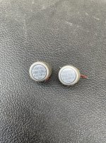
Bought this pair of Tamura microphone input transformers off yahoo.co.jp auctions for 3000 yen.

They are nominally 300 ohm / 2.7 kohm, meaning a 1:3 turns ratio, and, for my 250 microphone, a nominal 2250 ohm output impedance.

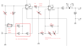
I plan to make a functioning "mule" from the Emerald circuit board, leaving out the RIAA filter and replacing the jumper gain setting with a stepped attenuator. I'll provide the 48 V phantom from a separate circuit board.
 

Attachments

  • i-img600x801-1702468202gdhkzx364.jpg
    i-img600x801-1702468202gdhkzx364.jpg
    143.4 KB · Views: 35
  • mic pre 1.png
    mic pre 1.png
    59.6 KB · Views: 37

rjm

Member
Joined 2004
Paid Member
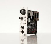
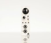
As inspiration, here's an example I found of "what I would build if I could". The Meris 440 Mic Preamp.
I love the straightforward layout and the classic instrumentation look. Those Bakelite knobs, toggle switches perfectly match the cream-white faceplate.
You can see the input and output transformers on the card.

In terms of features, there's the usual phase reverse and 48V phantom switches, as well as a -20 dB attenuator (pad). Then there's two 3-position EQ switches, tremble (off-1-2) and bass (off-1-2), an finally an external loopback for adding effects.

I note the gain control structure is divided into three parts, a "gain" control for the input amplifier, an attenuator (volume control) for the output signal, usually right in front of the output buffer, and somewhere a flat 20dB cut is also implemented.

I really need to get my hands on some schematics to see how all this is usually done.
 

Attachments

  • Meris_Mercury7_34-scaled.jpg
    Meris_Mercury7_34-scaled.jpg
    103.5 KB · Views: 32
  • Meris_Mercury7_front-scaled.jpg
    Meris_Mercury7_front-scaled.jpg
    63.7 KB · Views: 29
Last edited:

rjm

Member
Joined 2004
Paid Member
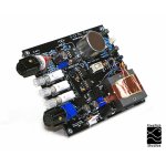
Huh. There are people selling kits. Although the board layout closely resembles the Meris 440 above, the X-12 from Fivefish Audio uses OPA134 op amps with the option of a discrete op amp in a 2520 package. The tone controls and effects loop are omitted, but the phase switch and pad are retained, along with the split gain/attenuation structure. This is really close to what I intended to build.
 

Attachments

  • x12profile-800x800.jpg
    x12profile-800x800.jpg
    109.3 KB · Views: 34
Last edited:

rjm

Member
Joined 2004
Paid Member
https://www.gearnews.com/heritage-audio-i73-pro/

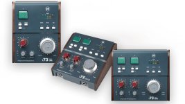
There is merit to the idea of adding the ADC to the mic preamp and giving it a USB output since the recording will be digital eventually. Unfortunately the analog side of many of these "audio interfaces" often isn't that great. The product above is at least an interesting step in the right direction.
 

Attachments

  • 28996-01232024075103.jpg
    28996-01232024075103.jpg
    61.9 KB · Views: 17
Last edited: