Cut to length, Wrap with felt and secure with rubber bands.
My personal observations were to flare only the Inlet side……add a ring of felt to the outside terminus…..and for Christ’s sake……port it out the rear or bottom!!!!!!
An interesting patent review of a resonance reducing port concept:
https://audioxpress.com/article/patent-review-bass-reflex-speaker-cabinet-having-a-recessed-port
The article also includes a short overview of other resonance reduction concepts at the end!
I was very surprised several years ago when I first saw this patent, since the Karlson coupler was patented many years before this patent. It seems like you can’t patent the same invention twice, nevertheless, sometimes this happens 🙂 .
I have implemented a similar concept in this my loudspeaker project. Here are some pictures of BEM (ABEC3) simulation illustrating an effect of the Karlson coupler of different length on the radiation impedance of the membrane (the red square in the picture below). The couplers length is L=1/4, 1/3 and 1/2 of the pipe length. As you you can see the coupler effects not only the pipe resonance (the coupler lowers efficiency of pipe resonance), but it is also lowers frequency of the Helmholtz resonance.
Last edited:
Remember - the flow goes as much out as it goes in.... its not an engine.... so a symmetrical port would be anticipated - the only departure would be due to the difference in the environment close to the port being either on the outside or the inside,,,
//
//
Engines and subwoofer enclosures are both air pumps. Engines are close to a BP6P enclosure.
Intake = high tune chamber.
Exhaust = low tune chamber.
Intake valves are always larger than exhaust valves.
High tune port is usually larger than low tune port.
Intake = high tune chamber.
Exhaust = low tune chamber.
Intake valves are always larger than exhaust valves.
High tune port is usually larger than low tune port.
Port geometry – port size
I printed and measured two port variants for my small 2way speaker, see post #449.Both ports have the same mouth opening diameter, but different central diameters and subsequently different lengths and flaring angles/rates.
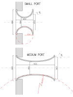
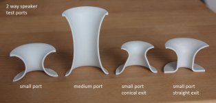
My test objective was
- to test whether the relevant Strouhal-related port diameter is only required for the port ends, as I assumed previously
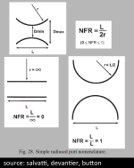
- to see how a very steeply curved port with NFR (“normalized flare rate” as defined by salvatti, devantier, button, see post #288 for a link) near 1 behaves at higher particle displacement distances.
- see if the port miniturization can be taken even further
- see whether conical or straight exterior end have any benefits. In short: they don’t, the straight end port of course also results in a different tuning.
The small port starts compressing and separating air flows at quite low volumes (see my next postings coming soon for chuffing/compression diagrams).
By calculating the respective Strouhal numbers I noted that increasing the mouth diameter beyond a flare exit angle of 30° does not bring any benefits and compression and low frequency noise sets in at exactly the respective effective diameter.
see the sketch above for the effective flare exit angle and respective effective port radius dimension to calculate the strouhal number.
The small port is too small to be useful for my project (of course....it's TINY). The steep curvature does not provide any benefit.
This matches the rule of thumb as defined in salvatti+al papers: max sensible curvature radius = port length.
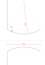
The elliptic wall geometry I used for the “medium port” resembles quite well a circular shape with an additional roundover at the ends and a “NFR” of 0,4 (port curvature radius slightly bigger than port length, see red circle in the first image above!).
Last edited:
Looks like you are making intake trumpets or velocity stacks for individual throttle bodies.

2 way speaker test ports ...
More test ports (with some mentioned already) for extensive measurements: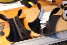
ports printed with PLA material in two halves, to be sanded, filled, sanded, primed for a smooth inner surface.
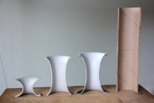
small, medium, big and cardboard tube port.
The "big" port just has a slightly more curved wall geometry than the "medium" port.
An explanation how I define my desired geometry and size will follow!
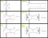
The "caps" on the port ends as shown on the right bottom should (and actually do!) force the air flow to stay laminar and don't allow separation of flow directions (or formation of a "jet"):
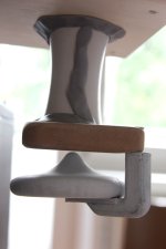
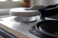
the impedance measurements show the "caps" (obviously) increase the effective weight of the port air (thus virtually extend port length) and very slightly lower the tuning. The tuning lowering effect is not very strong, because the air speed is not high compared to the central port section.
directing a port towards the floor or a wall could have a similar, positive effect.
the MDF "hoods" on the caps drawn in light grey were necessary to avoid high pitched turbulence hiss.
also a first test with thin bracing fins at the edge of the "caps" led to unbearable turbulent noise (photo of filling in process, the thin fins are way to weak ...):
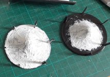
I'm of course not the first one with such an idea, again:
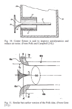
(excerpt from salvatti/devantier/button)
Last edited:
Port frequency responses - port resonance/enclosure resonance transmission behaviour
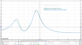
These graphs include a gated midfield (25 cm distance from driver) and a port nearfield response measurement.please keep in mind that for the front mounted ports there is some driver output bleeding into the port nearfield measurement!
I also included a midfield sealed enclosure (all ports closed) measurement in the first and 6th image, and in most other graphs the tube port measurement, as reference.
for the big port (which is the one I will use, due to the best chuffing/compression behaviour) I tried out several mounting versions.
here is an overview:
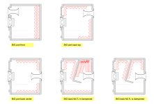
please note that the "mass loaded TL" version is just a crude and dirty quick trial setup. This would of course require simulation, adapting the line shape and driver/port positioning for reducing the line length resonance!
1) tube port mounted on the front baffle (see post #466 for a plan showing two ports, one of which was closed for the measurement) and sealed enclodsure:
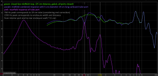
the midrange is strongly disturbed by port resonance and transmission of internal enclosure resonances.
the tube has a highly resonant diameter/length relation (5 cm/19 cm) and geometry and a big constant diameter transmitting internal resonance peaks.
this behaviour led to this whole thread!
2) small port on the front baffle:
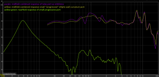
nearly no resonance peaks.
the small central port cross section seems to restrict transmission of enclosure resonances.
the very small lenght (net 4,2 cm) also compared to central diameter (2 cm) reduces the port resonance tendency. the resonance would happen somewhere below 4 kHz, there is barely anything there.
the only massive downside is the bad compression and flor separation behaviour, unfortunately!
3) medium port on the front baffle:
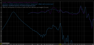
there is a 1,6 kHz peak around 12-14 dB below driver output, which corresponds to enclosure width AND effective port lenght, disturbing the combined output.
this peak is not as strong as the tube port resonance, of course!
4) big port on the front baffle:
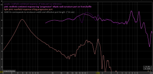
again, a 1,6 kHz peak corresponding to enclosure width AND effective port lenght, is slightly disturbing the combined output.
5) big port on the top back side:
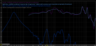
there is less output bleeding from driver to port, therefore the internal height resonance with it's pressure peak at the top is now clearly visible.
it's still not entirelly clear to me why this peak seems to be non-existent at the front mounted port.
EDIT: it might have to do with the driver-port exit distance. that is 30 cm with the back top mounted port!
the resonance peak however is nearly 20 dB below driver output and because it's mounted on the back does not interfere much with the driver output, thus it seemed quite acceptable, so here is the comparison to the sealed version:
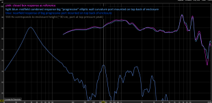
6) different versions of back mounted port, refer to overview plan above:

the centrally mounted back port is exactly behind the driver and resonates/transmits strongly at 1,6 kHz.
while it does not seem to influence the front output very much I wanted to see how "separating" driver and port would reduce this peak by turning the box into a "mass loaded TL" design.
This does the trick! too much dampening material however also reduces the port output.
the TL length resonance at 265 Hz could probably be eliminated or very much reduced by optimizing the line geometry and, more importantly, correctly positioning driver and port along the transmission line.
I still don't have a final conclusion, but it seems the top back mounted port is a viable option, eventually with a resonance absorber!
If I wanted to have a front mounted port I would probably try to "stuff" an optimized MLTL into the box.
Last edited:
Amazingly detailed write up! Thank you.
It surprises me how much fundamental output is lost for the highly damped TL version, considering there appears to be a free flowing passage for the air.
I think it's also interesting to consider, even in a 3-way, it's good to avoid any placement that shows higher frequency resonances since they could possibly be audible if stimulated by chuffing noise.
Will you be able to show how much the port caps helped in reducing onset of flow separation?
As we found that rectangular ports can reduce the onset of flow separation by having a more gradual wall curvature for the same rate of cross-section area growth, are you not tempted to use them instead of round?
Yes it is a surprise, but if you start thinking about damping, it's damping, it takes away energy and suddenly it makes sense.It surprises me how much fundamental output is lost for the highly damped TL version, considering there appears to be a free flowing passage for the air.
If you put stuffing inside a closed box and damping effect is seen in system response as lower Q and most notably in impedance plot as reduced impedance peak at main resonance, which really shows the woofer doesn't resonate as much at the resonance, with more damping in place. The damping material inside takes away energy from the woofer resonance. This is often the purpose with closed boxes, but you don't want that on bass reflex box, to dampen the lows because we want to maximize the lows (a resonance). Perhaps too simplified thought there, but that's the effect in general. Helmholz resonance gets dampened just like driver resonance would.
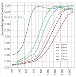
I speculate that if one is very selective with the damping material and it's thickness so that there is very low absorption coefficient on lows but ramps up where you'd need the damping, somewhere around box dimension wavelengths. It might be possible to increase difference between Helmholtz resonance peak and the mid leakage output at the port.
For example relatively thin Basotect, or just melamine foam/sponge, could work better than heavy / think fiberglass type insulation. I have not tested this, but would make sense if it worked 🙂 This would change the rule of thumb from "clear air path from driver to port" to more accurate "thin damping material at the walls".
Last edited:
It's the eggcrate foam at the "TL" bend between driver and port. This can be simulated easily with hornresp. It doesn't make much sense to do so (to dampen here!), therefore it's not common either!It surprises me how much fundamental output is lost for the highly damped TL version
Yes!Will you be able to show how much the port caps helped in reducing onset of flow separation?
Yes, thanks for reminding me!are you not tempted to use them instead of round?
Round ports are easier to print, smoothen and install so an easier studying material.
Last edited:
my statement might be misunderstood:I never use the dampening function in HR.
The dampening tool (in the loudspeaker wizard) is extremely useful! You should use it, if you design a 2-way ported speaker!
You should not put dampening material between driver and port, however.
But I also know you probably build subwoofers only 😊
Great and wonderful to see those measurements and I have to say that you beat me to it 🙂 😀 😀while it does not seem to influence the front output very much I wanted to see how "separating" driver and port would reduce this peak by turning the box into a "mass loaded TL" design.
This does the trick!
I still have a similar setup laying here (still in moving boxes lol)
Just didn't have time yet to get to it after we moved.
But yeah this is basically very much in line with what I was already predicting.
This issue is actually far more obvious with large full tower cabinets.
There is one other small drawback with a MLTL, and that is that the effective volume efficiency is a little lower compared to a plain rectangular box.
Meaning that you need a slightly bigger box (dimensions) for the same results.
This is nothing more then a result of mathematical geometry, since we are dealing with a sort of triangle instead of a rectangle.
Meaning that you can pack less surface area/volume basically.
Anyway, the entire concept works because of the low-pass filtering effect of a MLTL, especially with the damping material.
Which still makes me be curious about using an acoustic low-pass filter tube;
https://en.wikibooks.org/wiki/Acoustics/Filter_Design_and_Implementation#Low-pass_filter
Which I think is practically easier to construct compared to a band-stop filter (aka helmholtz absorber).
Mostly because we don't care about band-stopping just one frequency, but just cutting off everything above a certain frequency.
As long as we are roughly 4-5 octaves or so above the tuning frequency.
Probably a bit higher would be better.
I would pick the cut-off frequency just roughly an octave below the first resonance of the tube.
But I haven't done the practical calculations just yet.
🤣😂But I also know you probably build subwoofers only 😊
it was the other way around, if I remember correctly:you beat me to it
😎For internal cabinet resonances (standing waves), I would suggest going for a mass loaded transmission line (MLTL).
the interesting thing is that there is no strict distinction between "ported bass reflex" and "mass loaded transmission line".the effective volume efficiency is a little lower compared to a plain rectangular box.
in my case the TL is very short and basically just separates the driver from the port. I did not notice any relevant change of tuning frequency and output level (except for the badly overdampened version).
There is one other small drawback with a MLTL, and that is that the effective volume efficiency is a little lower compared to a plain rectangular box.
Meaning that you need a slightly bigger box (dimensions) for the same results.
This is nothing more then a result of mathematical geometry, since we are dealing with a sort of triangle instead of a rectangle.
Meaning that you can pack less surface area/volume basically.
For the same tuning frequency,
Positive flare = big and loud.
Negative flare = small and low.
Usually, both styles are more efficient per a given voltage than a regular BR enclosure.
- Home
- Loudspeakers
- Multi-Way
- Investigating port resonance absorbers and port geometries

