I have a troubling noise issue that I spent a fair bit of time diagnosing today. My amplifier (3e audio unit) is installed in my car, and is fed by a dc boost module to go from 12v to 48v. The amplifier is fed by a DSP, which runs on 12v. Because the DSP has single ended RCA outputs (not balanced), I modified the amplifier to accept the single ended input. I am getting a roughly 20hz tone (I think this may be PWM noise by a component in the car). My question is, is it possible the noise is being caused because the RCA cable signal ground is grounding to the 12v dsp and the 48v amplifier?
Here are the combinations I tried that made me suspect the signal ground:
DSP>3e amp=noise
Phone with usb c to rca converter>3e amp=no noise (rules out issue with amplifier)
DSP>amplifier/speaker outside of car (with long rca)=no noise (rules out issue with DSP)
DSP>commercial car audio amp=no noise (I'm not sure if car audio amps run fully on 12v throughout? Or they manage the signal ground differently?)
I also did several other things like run the dsp from a different 12v source to eliminate ground loops, tried different RCAs/shielding etc.
Another thing that makes me think an issue with the signal ground is that when I insert the RCA into the amp while it is carrying a signal from the dsp, I can start to hear the music when the middle signal pin makes contact without any noise, but when the ground connection is made the noise starts.
Any help would be greatly appreciated, I am stumped on how to address this!
In car audio, every component that accepts a signal has a noise cancelling input (either active or ground isolation). Your amplifier does not.
A ground loop isolator may be your best option.
Can you isolate the secondary ground on the 48v supply?
Is the amp running off of ±24 or straight 48v DC?
Schematic diagrams for any of the components in the system?
A ground loop isolator may be your best option.
Can you isolate the secondary ground on the 48v supply?
Is the amp running off of ±24 or straight 48v DC?
Schematic diagrams for any of the components in the system?
Hi Perry, thanks for the reply! By active noise cancelling, do you mean a balanced signal? Sorry, I am still fairly new to all of this.
Currently everything is isolated, meaning the amp and power supply are isolated from the chassis, and are only connected by the wires running from the power supply to the amplifier. There is a lot of info about grounding for the 120v crowd, less so for the 12v crowd, and I wasn't sure if things like star grounding to the chassis or adding a resistor between signal ground and chassis were needed in the 12v setting.
The amp runs on a single rail (+48/0) although I am also using a split rail power supply for another pair of amps, of which I have tested 1, and it also has the same noise issue.
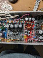
I do not have schematics, sorry. I'll post a picture of the +48/0 supply and 3e amp. My multimeter says that the input and output ground of the power supply have a very high resistance of roughly 1M ohm.
Currently everything is isolated, meaning the amp and power supply are isolated from the chassis, and are only connected by the wires running from the power supply to the amplifier. There is a lot of info about grounding for the 120v crowd, less so for the 12v crowd, and I wasn't sure if things like star grounding to the chassis or adding a resistor between signal ground and chassis were needed in the 12v setting.
The amp runs on a single rail (+48/0) although I am also using a split rail power supply for another pair of amps, of which I have tested 1, and it also has the same noise issue.
I do not have schematics, sorry. I'll post a picture of the +48/0 supply and 3e amp. My multimeter says that the input and output ground of the power supply have a very high resistance of roughly 1M ohm.
Attachments
When the amp is installed (and would produce clean audio with your phone), what's the resistance from the RCA input shields to ground (with nothing plugged into the RCA jacks)?
Are you using this with a normal head unit? Normal as in, the output RCA shields read 0 ohms to ground?
Are you using this with a normal head unit? Normal as in, the output RCA shields read 0 ohms to ground?
On the amp RCA input shield, measured to the battery negative terminal, I get about 4M Ohm.
On the DSP RCA output shield, measured to battery negative terminal, I get about 1.1 Ohm.
These are with no RCA cables installed.
Here is a photo of the layout, if it makes anything easier:

On the DSP RCA output shield, measured to battery negative terminal, I get about 1.1 Ohm.
These are with no RCA cables installed.
Here is a photo of the layout, if it makes anything easier:
What sort of modifications did you do to the input of the amp?
The output of an audio component is generally the same ground as the power ground for that component. It's the input that has isolation.
Do you have a ground loop isolator? Or does a friend have one laying around that you could borrow?
What's feeding signal into the DSP?
The output of an audio component is generally the same ground as the power ground for that component. It's the input that has isolation.
Do you have a ground loop isolator? Or does a friend have one laying around that you could borrow?
What's feeding signal into the DSP?
The modification was adding an OP amp and removing a couple resistors. The amp was originally configured to use a balanced signal, and the manufacturer recommends this change if it is being fed a single sided input.
Would it be possible to tie the 48v ground to the 12v ground (effectively making the 48v power supply "unisolated")?
I do not have a ground loop isolator, but I can get one. I have heard they can create changes in the tonality of the signal, so I'm hesistant if there is another solution.
The DSP is fed by coaxial digital signal (and bluetooth eventually hopefully)
Thanks again for all the help!
I know of no problem driving a balanced input with an unbalanced signal.
People say a lot of things and expectations can skew reality. If you want to believe that the LOC is evil, it will sound awful. For most people, they would never hear a difference with/without it. There are also differences in quality of manufacture and some are directional.
You can't provide any diagrams so it's difficult to know what you can or can't do.
Does this amp have 24v on all speaker terminals when it's powered up? You'll need to use the 48v supply secondary ground as the reference (black meter probe).
What's powering the preamp section of the amplifier? Does it have ±supply voltage?
Both speaker wires measure +24 (well, 22.6ish) as measured from the ground side of the 48v input. Here is the portion of the manual for the amp module where it talks about the modification I did to the amp:

I am not sure about power for the preamp section of the amp, sorry. I did measure the ground side of the 48v supply to the ground side of the 12v supply, and saw 3.5mv.
I am not sure about power for the preamp section of the amp, sorry. I did measure the ground side of the 48v supply to the ground side of the 12v supply, and saw 3.5mv.
Without a full diagram, I don't understand why they did this. For the most part (for all I know of), a balanced input will work perfectly fine with unbalanced signals).
For the preamp voltage use the same ground but place the red probe on pins 4 and 8 of the 2-channel op-amps.
For the preamp voltage use the same ground but place the red probe on pins 4 and 8 of the 2-channel op-amps.
Pin 8 was showing 35v, and several other pins were at 17.5 or so.
I tried connecting the 12v and 48v grounds, and this did nothing to reduce the noise. I also tried holding a wire on the shield ends of the rca (adding another signal ground path) and this reduced the noise a fair bit. I am still confused why with the phone the amp doesn't pick up any noise, and with another amp there isn't any noise either, but somehow the two of them together create the issue. Thanks again for your help Perry!
I tried connecting the 12v and 48v grounds, and this did nothing to reduce the noise. I also tried holding a wire on the shield ends of the rca (adding another signal ground path) and this reduced the noise a fair bit. I am still confused why with the phone the amp doesn't pick up any noise, and with another amp there isn't any noise either, but somehow the two of them together create the issue. Thanks again for your help Perry!
They match, the chips just look a bit different. The two "resistors" removed, and one placed in the different location are all zero ohm, and I found it easier to bridge with solder than hold that tiny guy in place.
I have an idea that might make things easier. The amp I am using for rear fill also has the same exact noise, and it is a much more simple layout, based on the lm3886. Here is a photo of the PCB:
https://www.aliexpress.us/item/2255...lgo_pvid=5c5cd811-2f49-4e68-88fd-cba6d63ba357
Maybe I have a grounding issue that is common to all of my amplifier boards?
They call for removing the r17 and r21 resistors, and moving one of them to the r123 position. These resistors are both 0 ohm, so instead of placing a 0 ohm resistor in that position, I just did a solder bridge because it was easier.
Yes I shorted the - and ground, this is done at the rca socket.
The 3886 boards get their signal from the dsp as well, so identical to the class D boards. The only difference is that they are receiving power from a different power source (12v to +/- 30v)
Yes I shorted the - and ground, this is done at the rca socket.
The 3886 boards get their signal from the dsp as well, so identical to the class D boards. The only difference is that they are receiving power from a different power source (12v to +/- 30v)
I apologize for missing the 0 ohms.
You wrote:
I also tried holding a wire on the shield ends of the rca (adding another signal ground path)
From the RCA shields to which ground? The 48v ground or to the primary ground?
You wrote in response to DCV on pins 4 and 8:
Pin 8 was showing 35v, and several other pins were at 17.5 or so.
Clarify.
Which ground were you using (should have been the 48v ground)?
DCV on pins 4 and 8 using the 48v ground?
How/where are they defining IN-?
Last edited:
- Home
- General Interest
- Car Audio
- Issue with signal ground on diy amp in my car?