- We many times wonder what if that SMPS brick that feeds the Raspberry Pi or the mini PC or the MiniDSP or the Squeezebox or the DAC or the desktop Class-D amp etc. was a linear PSU? How such wonder boxes would perform without switching noise polluting their rail and most crucially their many times interconnected ground?
- What if we had a simple and strong linear PSU instead of fixed SMPS brick adapters that it could cover the voltage range for such applications by only setting it up with a jumper?
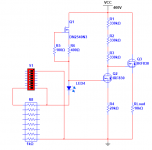
- Enter the L-Adapter. A versatile Sziklai pair stabilizer / capacitance multiplier based on LED voltage reference.
- Its output voltage is how many LED + trimmer minus one Vbe. Roughly 1.5V to 20V range. Move the jumper, trim Vout, ready. Connect the load.
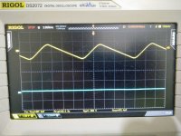
- Is it any good? Yes its good. Not noisy at all and stable. For 1.5V input ripple it produces 1.5mV thick DC line. For 3 Ampere load it measures 0.02Ω output impedance. Which is flat and extended in frequency. When you pulse it the recovery is clean of ringing. Because there is no feedback between the output and the voltage reference. We want a general purpose PSU staying insensitive to random gear loading peculiarities.
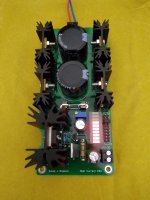
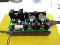
- The recipe isn't anything new but the details are well researched. Low noise unity gain reference, but adjustable too. Which LED bar with which CCS experimentally chosen between many styles for very good Vref stability, what pair of transistors, the layout. Various ways to sink it, accepts quality TO-220 bridge diodes, two reservoir capacitors, fused like a Π filter. The board is 136mm x 63mm.
- What about its output current ability? Well, it uses a 15A audio amp grade TO-3P pass transistor. But that alone says nothing much. Its also the transformer the diodes the reservoirs the sinking the load's average consumption. Say up to 7.5A average can be catered for.
- For any light or heavy current application it takes that the chosen Tx the bridge diodes and the reservoir caps won't lose the plot for a target Vout. That's about rectification and filtering basics. It does not like less than 2.5V input-output voltage difference. That's the DC difference between C4 and the output. Can probe that between the fuse and V+ out. Or across D11. Although it keeps working on smaller differences it gets progressively goofy. If you see the LEDs dimming a bit its tell tale you crossed the raw DC section's losses good limit.
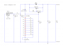
- Here is a schematic with typical reservoir caps values and some pictures. That soldering iron pulled 55W peak from the mains through the PSU to boot and idled at 12W. The scope pic displays Vin ripple on C4 vs Vout status captured at a point when the iron was still pulling hard to heat up started from room temperature cold state.
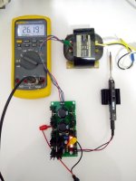
The Fluke reads C4's raw DC level in another picture. Started at 27V idle with worst loss of 4V during the soldering iron's boot cycle (trafo, diodes, rippleV). At 23V raw DC for 18V output to the iron, that trafo and reservoir caps passed the 2.5V Vin-Vout criterion by double margin. Other type & quality trafo or diodes could lose more or less steam of course. Higher value reservoir caps would achieve less ripple voltage but would also make the diodes work harder. Since the worst raw DC level sufficed, better not increase the caps value in this case.
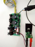
The example has 4xMUR860 & 2x4700uF/35V B41231 EPCOS/TDK. Also a 38mm tall Q2's sink. Which sufficed due to the irregular current pull of the micro controlled soldering iron. Can it do an RPi3? Yes I tested it with Wi-Fi and streaming vids on the Raspbian OS. Can it do a 12V Windows 10 Cherry Trail mini PC? Yes I tested it. Watched a whole movie stored in a mechanical 2.5 inch USB Hard Disk attached to it. The PC was at the same time charging an OnePlus X phone from a spare USB output so I pushed it further. I now used lower voltage and smaller size transformers than that R-Core. EI or toroidal of average quality. They and the sinks sufficed again because of the irregular current pull of computers with idling gap periods. 45C on the 38mm 35C on the 25mm ones for the diodes. Minimal RPi use shouldn't need diode sinks at all.
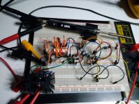
- In the final black & gold boards there are correct Q1 Q2 designations. On the green prototype first photo you may spot Q3 Q4 relic prints, please ignore. PCB size is 136mmX63mmX2mm. Its mounting holes diameter is 3.6mm. Their horizontal center to center distance is 127mm. Their vertical center to center distance is 54mm.
- I will be editing & enhancing post #1 in later installments.
- 25/6/2019 Build guide added (includes circuit description & BOM) - attachments rearranged
- What if we had a simple and strong linear PSU instead of fixed SMPS brick adapters that it could cover the voltage range for such applications by only setting it up with a jumper?
- Enter the L-Adapter. A versatile Sziklai pair stabilizer / capacitance multiplier based on LED voltage reference.
- Its output voltage is how many LED + trimmer minus one Vbe. Roughly 1.5V to 20V range. Move the jumper, trim Vout, ready. Connect the load.
- Is it any good? Yes its good. Not noisy at all and stable. For 1.5V input ripple it produces 1.5mV thick DC line. For 3 Ampere load it measures 0.02Ω output impedance. Which is flat and extended in frequency. When you pulse it the recovery is clean of ringing. Because there is no feedback between the output and the voltage reference. We want a general purpose PSU staying insensitive to random gear loading peculiarities.
- The recipe isn't anything new but the details are well researched. Low noise unity gain reference, but adjustable too. Which LED bar with which CCS experimentally chosen between many styles for very good Vref stability, what pair of transistors, the layout. Various ways to sink it, accepts quality TO-220 bridge diodes, two reservoir capacitors, fused like a Π filter. The board is 136mm x 63mm.
- What about its output current ability? Well, it uses a 15A audio amp grade TO-3P pass transistor. But that alone says nothing much. Its also the transformer the diodes the reservoirs the sinking the load's average consumption. Say up to 7.5A average can be catered for.
- For any light or heavy current application it takes that the chosen Tx the bridge diodes and the reservoir caps won't lose the plot for a target Vout. That's about rectification and filtering basics. It does not like less than 2.5V input-output voltage difference. That's the DC difference between C4 and the output. Can probe that between the fuse and V+ out. Or across D11. Although it keeps working on smaller differences it gets progressively goofy. If you see the LEDs dimming a bit its tell tale you crossed the raw DC section's losses good limit.
- Here is a schematic with typical reservoir caps values and some pictures. That soldering iron pulled 55W peak from the mains through the PSU to boot and idled at 12W. The scope pic displays Vin ripple on C4 vs Vout status captured at a point when the iron was still pulling hard to heat up started from room temperature cold state.
The Fluke reads C4's raw DC level in another picture. Started at 27V idle with worst loss of 4V during the soldering iron's boot cycle (trafo, diodes, rippleV). At 23V raw DC for 18V output to the iron, that trafo and reservoir caps passed the 2.5V Vin-Vout criterion by double margin. Other type & quality trafo or diodes could lose more or less steam of course. Higher value reservoir caps would achieve less ripple voltage but would also make the diodes work harder. Since the worst raw DC level sufficed, better not increase the caps value in this case.
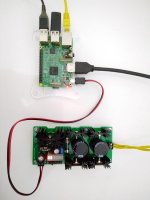
The example has 4xMUR860 & 2x4700uF/35V B41231 EPCOS/TDK. Also a 38mm tall Q2's sink. Which sufficed due to the irregular current pull of the micro controlled soldering iron. Can it do an RPi3? Yes I tested it with Wi-Fi and streaming vids on the Raspbian OS. Can it do a 12V Windows 10 Cherry Trail mini PC? Yes I tested it. Watched a whole movie stored in a mechanical 2.5 inch USB Hard Disk attached to it. The PC was at the same time charging an OnePlus X phone from a spare USB output so I pushed it further. I now used lower voltage and smaller size transformers than that R-Core. EI or toroidal of average quality. They and the sinks sufficed again because of the irregular current pull of computers with idling gap periods. 45C on the 38mm 35C on the 25mm ones for the diodes. Minimal RPi use shouldn't need diode sinks at all.
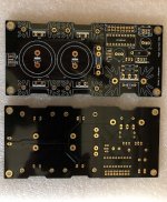
- In the final black & gold boards there are correct Q1 Q2 designations. On the green prototype first photo you may spot Q3 Q4 relic prints, please ignore. PCB size is 136mmX63mmX2mm. Its mounting holes diameter is 3.6mm. Their horizontal center to center distance is 127mm. Their vertical center to center distance is 54mm.
- I will be editing & enhancing post #1 in later installments.
- 25/6/2019 Build guide added (includes circuit description & BOM) - attachments rearranged
Attachments
-
 IMG_20190413_034624.jpg344.6 KB · Views: 8,538
 -
 IMG_20190414_181710.jpg386 KB · Views: 8,325
 -
 IMG_20190415_142512.jpg501.7 KB · Views: 7,402
 -
 IMG_20190413_153127.jpg372.9 KB · Views: 7,156
 -
 IMG_20190417_155049.jpg321 KB · Views: 7,832
 -
L-Adapter Guide.pdf292.2 KB · Views: 2,834
-
 L-Adapter schematic.png21.3 KB · Views: 5,262
 -
 Black LA.jpeg147.7 KB · Views: 5,160
 -
 L-Adapter_BB.jpg555.5 KB · Views: 3,077
 -
 IMG_20190422_040533.jpg332 KB · Views: 2,867
") .
.