Last, but (hopefully) best ever modified and complete NAD 3020

Member
Joined 2021
Paid Member
So recap finished today. Next I will move on to start the FET mod
 

Attachments

  • IMG_20240421_132032.jpg
    IMG_20240421_132032.jpg
    388.4 KB · Views: 80
Member
Joined 2021
Paid Member
So I've finished the heat sink. Took a while to get it the way I wanted it, now I can start looking at the mod
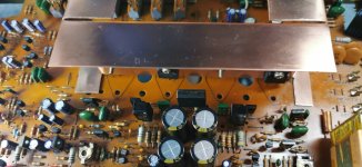
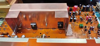
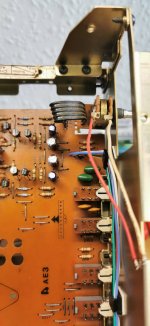
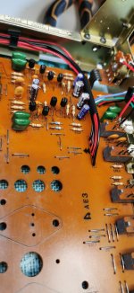
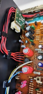
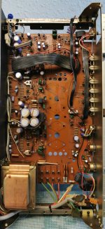
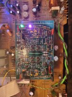
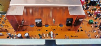
So this heat sink isn't going to work. I should have realised, BJT'S are reversed positions for the PNP's, and that puts the gate on the wrong side. So back to the drawing board with this. May even make one from scratch
 
Member
Joined 2021
Paid Member
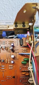
so having scrapped the previous heatsink idea(and attaching with the heat pads,Ive made the basic shape now and dry fitted the FETS
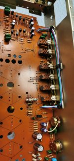
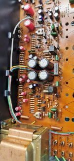
Doing it this way verticaly, it gives me much more on the board to play with for the mod
 

Attachments

  • IMG_20240426_163340.jpg
    IMG_20240426_163340.jpg
    381.1 KB · Views: 79
  • IMG_20240426_163413.jpg
    IMG_20240426_163413.jpg
    314.6 KB · Views: 79
Member
Joined 2021
Paid Member
I don't think this looks too bad,and I now have the feet attached so I can secure to the board and ground it
 

Attachments

  • IMG_20240428_123406.jpg
    IMG_20240428_123406.jpg
    301.4 KB · Views: 53
  • IMG_20240428_123323.jpg
    IMG_20240428_123323.jpg
    280 KB · Views: 52
Administrator
Joined 2007
Paid Member
It looks as substantial as the original (as much metal to dissipate the heat) and it is vertical and so yes, its probably as good as the original if not better.
 
Member
Joined 2021
Paid Member
So I've done the first part of the rewire. The objective here is to get everything out of the way as the ribbon cables got in the way
 

Attachments

  • IMG_20240502_161831.jpg
    IMG_20240502_161831.jpg
    300.5 KB · Views: 40
Member
Joined 2021
Paid Member
The volume control board has been tidied up and the connections have been moved to underneath the board to give me room for the JLA2 cable alterations
 

Attachments

  • IMG_20240503_084221.jpg
    IMG_20240503_084221.jpg
    247.2 KB · Views: 42
  • IMG_20240503_090515.jpg
    IMG_20240503_090515.jpg
    256.6 KB · Views: 42
  • IMG_20240503_090448.jpg
    IMG_20240503_090448.jpg
    296 KB · Views: 45
Member
Joined 2021
Paid Member
Starting to come together now. Most of the wiring is finished so it will sson be time to start on converting to the FETS
 

Attachments

  • IMG_20240504_124508.jpg
    IMG_20240504_124508.jpg
    313.2 KB · Views: 33
  • IMG_20240504_124455.jpg
    IMG_20240504_124455.jpg
    289.1 KB · Views: 36
  • IMG_20240504_124502.jpg
    IMG_20240504_124502.jpg
    277.4 KB · Views: 35
  • Like
Reactions: 1 user
Member
Joined 2021
Paid Member
the re wire has been pretty successfull, it took a long time, but it was worth it, give alot more room.This is what it looked like originaly with that big ribbon cable obstructing the regulated supply cable
 

Attachments

  • IMG_20240413_094644.jpg
    IMG_20240413_094644.jpg
    478.2 KB · Views: 39
  • Like
Reactions: 1 users
Administrator
Joined 2007
Paid Member
Those ribbons can have a tendency to fracture if moved around to much. It all looks very neat (y)
 
Member
Joined 2008
Nice work, should be a great amp.
I did same with sx 780
Started small but then grew quite a bit
 

Attachments

  • 20240321_162625.jpg
    20240321_162625.jpg
    485.1 KB · Views: 29
  • 20240321_162636.jpg
    20240321_162636.jpg
    378.2 KB · Views: 28
  • 20240321_162640.jpg
    20240321_162640.jpg
    379.2 KB · Views: 27
  • 20240321_162649.jpg
    20240321_162649.jpg
    474.9 KB · Views: 34
  • Like
Reactions: 1 users
Top