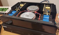
I have recently come in to possession of a dual mono mosfet amp from the early 90's
It's a Linx branded amp but I understand it was a small custom production run and doesn't have a model name per se. It appears to be a dual mono version of a Linx Pulsar - regardless, there is little info about these amps online. Linx was a small but well regarded New Zealand amp maker that Wharfedale picked up in the late 80's and then ceased to exist some time in the 90's.
The seller claimed 2 X 280W RMS ino 8 ohms, 450 watts in to 4 ohms which seems like a lot of power. I haven't measured the amp's power output (don't have equipment).
The amp itself is quite heavy (15-20kg?)
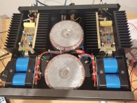
Each channel has its own power supply supplying +/- 75VDC.
Each power supply has 2x 10,000uF 75V caps (Sprague Powerlytic 36DE).
There are 4 output devices per channel, marked SML BUZ906D G9418Y and SML BUZ901D R9404Y.
There are 3 small-ish electrolytic caps per channel (2x 47uF 100V, 1x 25v 220uF)
Near each line input there is a polypropylene (?) 5.0+/- 10% 200V SiderealKaps capacitor
There is one potentiometer per channel
I have measured the DC offset at each channel's output, left = 1-2mv (fluctuates), right = 7-9.5mv (fluctuates) (was 20mv at cold turn on)
I fixed a buzzing noise coming through the speakers by re-tightening the star ground nut for each channel, there is now only a faint hiss/hum from each speaker which is only audible with one's ear right against the speaker
I have 4 questions:
1. The heatsinks on the right channel are somewhat hotter than the heatsinks on the left channel. I can rest my hand on the left heatsinks for about 10 seconds before feeling burned, while I can only rest my hand about 2.5 seconds on the right heatsinks before feeling burned.
I am assuming this is because of the higher DC offset voltage. Can I fix this by simply adjusting the potentiometer until I get 0VDC at the speaker terminal? If not how would I go about fixing it?
2. I like the amp's sound but it doesn't seem to have the resolution/soundstage I was hoping for. Are there any ways I can service or modify the amp to increase the sound quality?
I have a few ideas:
I am handy with a soldering iron and multimeter but haven't worked on amps before. Also, I don't want to spend too much.
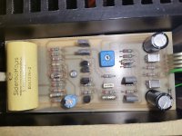
3. There are some small silver coloured caps on the input/driver boards that look like they may be electrolytics but I am not sure. Are these electrolytic caps? And would there be worth replacing? You can see these in the photos I've attached.
4. I am under the assumption that it wouldn't be a good idea to replace the main PSU filter caps if the amp seems to be working OK. (They're big, and there's four of them ($$$).) Am I correct in thinking this or would replacing them have a good impact on sound quality?
Thanks in advance!
It's a Linx branded amp but I understand it was a small custom production run and doesn't have a model name per se. It appears to be a dual mono version of a Linx Pulsar - regardless, there is little info about these amps online. Linx was a small but well regarded New Zealand amp maker that Wharfedale picked up in the late 80's and then ceased to exist some time in the 90's.
The seller claimed 2 X 280W RMS ino 8 ohms, 450 watts in to 4 ohms which seems like a lot of power. I haven't measured the amp's power output (don't have equipment).
The amp itself is quite heavy (15-20kg?)
Each channel has its own power supply supplying +/- 75VDC.
Each power supply has 2x 10,000uF 75V caps (Sprague Powerlytic 36DE).
There are 4 output devices per channel, marked SML BUZ906D G9418Y and SML BUZ901D R9404Y.
There are 3 small-ish electrolytic caps per channel (2x 47uF 100V, 1x 25v 220uF)
Near each line input there is a polypropylene (?) 5.0+/- 10% 200V SiderealKaps capacitor
There is one potentiometer per channel
I have measured the DC offset at each channel's output, left = 1-2mv (fluctuates), right = 7-9.5mv (fluctuates) (was 20mv at cold turn on)
I fixed a buzzing noise coming through the speakers by re-tightening the star ground nut for each channel, there is now only a faint hiss/hum from each speaker which is only audible with one's ear right against the speaker
I have 4 questions:
1. The heatsinks on the right channel are somewhat hotter than the heatsinks on the left channel. I can rest my hand on the left heatsinks for about 10 seconds before feeling burned, while I can only rest my hand about 2.5 seconds on the right heatsinks before feeling burned.
I am assuming this is because of the higher DC offset voltage. Can I fix this by simply adjusting the potentiometer until I get 0VDC at the speaker terminal? If not how would I go about fixing it?
2. I like the amp's sound but it doesn't seem to have the resolution/soundstage I was hoping for. Are there any ways I can service or modify the amp to increase the sound quality?
I have a few ideas:
- loosen, clean, and tighten any mechanical connections
- replace the small electrolytic caps (there's only 6 of them in the amp)
I am handy with a soldering iron and multimeter but haven't worked on amps before. Also, I don't want to spend too much.
3. There are some small silver coloured caps on the input/driver boards that look like they may be electrolytics but I am not sure. Are these electrolytic caps? And would there be worth replacing? You can see these in the photos I've attached.
4. I am under the assumption that it wouldn't be a good idea to replace the main PSU filter caps if the amp seems to be working OK. (They're big, and there's four of them ($$$).) Am I correct in thinking this or would replacing them have a good impact on sound quality?
Thanks in advance!
Attachments


1. It could be related to the quiescent current setting. There is usually an optimum that depends on the circuit. Don't touch it if you don't know what the correct value is or how it should be measured, as turning it up too high could be destructive.
3. The cylindrical, silvery capacitors with a wire on each side are polystyrene or polypropylene capacitors, which are technically the best types of film capacitors.
The rectangular silvery capacitors look like Siemens/Epcos stacked metallized MKT capacitors.
3. The cylindrical, silvery capacitors with a wire on each side are polystyrene or polypropylene capacitors, which are technically the best types of film capacitors.
The rectangular silvery capacitors look like Siemens/Epcos stacked metallized MKT capacitors.
Last edited:

1) the dc offset is fine as you reported. My Assumption is the blue pot is used to adjust the mosfet bias current but in order to do that you need to determine
1) which direction to turn it, usually cw increases bias
2) where to measure the bias current.
3) what it should be set too.
More bias more heat
without a schematic you have to figure it out but you need to understand how it could have been designed.
I’d leave it alone and would not change the ecaps
The BUZ's are single die lateral FET's and these would normally be biased to around 100 ma per pair (in the absence of any other information). The fact the heatsinks burn (your words) suggest the current is probably quite a bit higher than this.
So you need to find out the correct value before you can begin or else make the decision that its running to hot and adjust the current to a sensible value. .
So you need to find out the correct value before you can begin or else make the decision that its running to hot and adjust the current to a sensible value. .
Does the lid have an insulating layer to prevent the transformer mounting bolts/hardware from touching it should the lid get depressed down? If not I'd recommend adding this to prevent any chance of a shorted turn across those toroidal transformers (but without blocking any vent slots of course).
Likely old school polycarbonate, they were common back then.The rectangular silvery capacitors look like Siemens/Epcos stacked metallized MKT capacitors.
One thing I don't see is protection components for the MOSFET gates - normally back-to-back zeners or 1n4148+zener combination are used to prevent the gate oxide puncturing on a transient or other failure. Without that MOSFETs are much less robust. They might be mounted on the MOSFETs directly though.
Thank you everyone for your input
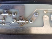
On the left channel, I looked at the PCB containing the mosfets, and found they weren't soldered in properly. It looks like someone has replaced them at some stage and forgot to solder them in properly before reassembling the amp. I was surprised the left channel worked as well as it did. Nevertheless I applied solder and reassembled. No huge change to the sound though.
On the right channel, the heat output is now much cooler. All I did was disassemble enough to look under the mosfet PCB to check soldering, then reassemble and tighten down the nuts holding the mosfets to the heatsink. (there were a few somewhat loose ones). The mosfet case (which the nuts/bolts secure against) is the mosfet source. Could a loose connection here have caused the right channel to be producing a lot more heat?
Would it be a good idea to solder the screws... in case there is a corroded/poor connection between the PCB traces and the screws?
I took a look at the board the mosfets are mounted to, and no, there are no diodes. However, in datasheets I've found for the mosfets, they refer to having an "integral protection diode" - is this what you mean?One thing I don't see is protection components for the MOSFET gates - normally back-to-back zeners or 1n4148+zener combination are used to prevent the gate oxide puncturing on a transient or other failure. Without that MOSFETs are much less robust. They might be mounted on the MOSFETs directly though.
The transformers are OK, the coils are well insulated and the mounting hardware is grounded to the chassis from belowDoes the lid have an insulating layer to prevent the transformer mounting bolts/hardware from touching it should the lid get depressed down? If not I'd recommend adding this to prevent any chance of a shorted turn across those toroidal transformers (but without blocking any vent slots of course).
Thanks, I will use it for a bit longer before more closely evaluating the sound.If in storage for long, use for a week or so to give the caps time to reform.
On the left channel, I looked at the PCB containing the mosfets, and found they weren't soldered in properly. It looks like someone has replaced them at some stage and forgot to solder them in properly before reassembling the amp. I was surprised the left channel worked as well as it did. Nevertheless I applied solder and reassembled. No huge change to the sound though.
On the right channel, the heat output is now much cooler. All I did was disassemble enough to look under the mosfet PCB to check soldering, then reassemble and tighten down the nuts holding the mosfets to the heatsink. (there were a few somewhat loose ones). The mosfet case (which the nuts/bolts secure against) is the mosfet source. Could a loose connection here have caused the right channel to be producing a lot more heat?
Would it be a good idea to solder the screws... in case there is a corroded/poor connection between the PCB traces and the screws?
Attachments

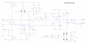
I spent this afternoon creating a schematic of the amp. Can anyone comment on the amp's design? Or how I could go about modifying it to decrease distortion / get a cleaner sound? Is there a way I can tell what the bias current should be from looking at the schematic?
Sorry, I do have some understanding of electronics but very little knowledge of amp design.
Please excuse the poor layout of the schematics, I was trying to keep the components in line with where they were on the PCBs so I wouldn't get too confused
Sorry, I do have some understanding of electronics but very little knowledge of amp design.
Please excuse the poor layout of the schematics, I was trying to keep the components in line with where they were on the PCBs so I wouldn't get too confused
Attachments

A loose gate could cause a lot of heat to be generated, I don't immediately see how a loose source could do that.
Regarding the transformer: if the mounting hardware gets in contact with both the lid and the bottom of the enclosure, then you may get the problem Mark wrote about, no matter how well the transformer is insulated.
Regarding the transformer: if the mounting hardware gets in contact with both the lid and the bottom of the enclosure, then you may get the problem Mark wrote about, no matter how well the transformer is insulated.
You don't understand the problem - if the mounting stud contacts the lid of the case then the stud and the case together form a single shorted turn in the transformer and will be extremely bad news (quite possibly hundreds or thousands of amps may flow). You need to ensure this cannot happen.The transformers are OK, the coils are well insulated and the mounting hardware is grounded to the chassis from below
Well that would make it difficult to remove them again without lifting pads on the PCB which isn't a great idea. Maybe add crinkle washers to apply constant pressure to the PCB pad. Or just clean, tighten. TO3 and similar packages are always problematic for mounting which is (I suspect) why they became obsolete.Would it be a good idea to solder the screws... in case there is a corroded/poor connection between the PCB traces and the screws?
That makes perfect sense, thanks for the explanation. Definitely want to avoid that....You don't understand the problem - if the mounting stud contacts the lid of the case then the stud and the case together form a single shorted turn in the transformer and will be extremely bad news (quite possibly hundreds or thousands of amps may flow). You need to ensure this cannot happen.
The amp seems to be improving... was using a poor quality power cable (number of solder joins, and two international plug adapters in series) which I replaced with a standard one which had a good influence on the sound.
The heat seams to have equalized between the channels. Actually, the left side is now hotter than the right side.
I read an article about replacing trim pots in amps to improve the sound - apparently the contacts corrode on cheap trimpots.
If the heat seems to be fluctuating somewhat could this potentially be caused by poor/corroded trimpots affecting the bias current?
Naresh, the amp has improved considerably after a week of playing music through it. I assume it had been in storage for some time based on my interactions with the seller.
I have ordered replacement capacitors and will see if there is further improvement after recapping. The existing caps appear to be originals (around 28 years old) so I'm sure fresh ones will make a difference. Anyway it will be interesting to see.
I have ordered replacement capacitors and will see if there is further improvement after recapping. The existing caps appear to be originals (around 28 years old) so I'm sure fresh ones will make a difference. Anyway it will be interesting to see.
A typical way of drawing this type amp like this:
Al values and variation of stabilising also. There is a lot of Goldmund amp (uses "the same circuit upside down with j-fet input and driver for the mosfet output. Goldmund uses current sorce here stiped with driver transistors "stippeled"):
If you change the circiut with driver transistors or any other circiut mod you also have to change stabilising capasitors.
Input capasitor AND C1 is werry important for sound and bandwith the amp will play in the low frequensy region spessially.
I havent drawed your shematic but the amp is somwat typical.
It dont have the best measurments but run in the group Sounds Good. and that is in a high degree caused by the AButput stage, almoust Unbreakable
You can by ready or built kits with similar circuit that wil fit in your case..
if that would not bee a to big a challenge for a handyman.?
I recapped the amp a few weeks ago and the sound has improved a lot
A lot of the background "hash" has vanished, the sound is now a lot cleaner.
Capacitor burn in is obviously a thing.
Initially after recapping the sound was very piercing and fatiguing, even my brother (non-audio-guy) commented on how shrill it sounded. However after a week of playing music the sound improved a lot and is now much better than before recapping.
- Home
- Amplifiers
- Solid State
- Modifying/servicing a mosFET amp - what to do?