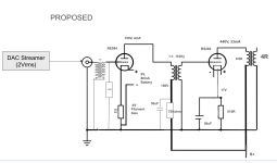
Hi everyone, I am pursuing a new pair of monoblocks. RE084 driving an RS282. Would like your thoughts on the design. I borrowed the operating points RE084 from Ale and the RS282 from RobDHT.
My main concern is if the RE084 will have enough swing to drive the RS282 to full output. My goal is to get 10-15 watts of clean class A using my DAC streamer as source (2Vrms). So, any thoughts on this would be appreciated. I have attached the schematic, curves and data sheets for each tube.
Thanks!
Pat
Attachments
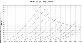
You cannot get 10-15W output power if the power tube is only dissipating 15W. In your schematics you will get some 3.5W. Need higher anode voltage and current for the rs282. It doesn't look like an efficient tube in Class A SE, so you will need at about 900V/50mA to get about 10W and about 1.1KV/60mA for 15W.
The RE084 is ok in your schematics but is on the weak side for 10-15W amp, IMHO.
The RE084 is ok in your schematics but is on the weak side for 10-15W amp, IMHO.
Last edited:
If you are worried that your resistor may be too big, just use a resistor divider.
If my math is right, a 7.5K resistor at the bottom of the resistor divider and a 27K resistor at the top of the divider will get you down to 150v at the junction. Best part is that you don't have to add in a 500K bleed down resistor for the cap.
With that setup you will have 24ma running through the upper resistor and 20ma running through the lower resistor. You will need to make sure your power supply can handle the additional 20ma of current and you will need a very beefy 27K ohm resistor.
Check out the specs of the resistors you use and see the max voltage drop they can safely take. Generally speaking 500-650V drop is too much for 1 resistor. If want to do it with one RC you will need "special" resistors. But you can do multiple RC's for better filtering plus one resistor to ground to discharge the caps when switch off. No need to run large current for 4 mA into the RE084. Can run 5 mA in total and do 3 RC's with 43K +30uF and then 150K to ground. Power dissipation into the each 43K will be just over 1W and 0.15W into the the 150K. So can use 5W resistors for the 43K and 1W for the 150K.Thanks 45. B+ can be modified to 800V, the only downside is that this is a shared power supply and thus a large resistor will be needed to bring 800V down to 150V. Do you believe that this large resistor will cause adverse impact to transient response? Dynamics?
With 800V, if you bias at 40mA you will get about 7W. That's about the max you can get with 9.6K transformer.
RS282 has very high Ri
from the datas:
S=5.5mA/V, u=12.5
Ri=u/S=12.5/0.0055(A/V)=2273 ohm
It is very difficult to prepare a good output transformer...
Has to be very high primary inductance in [Hy], probably more than 100Hy,
for decent bass response.
...
Also check the same thing for RS084
S=2mA/V, u=16
Ri=u/S=16/0.002(A/V)=8000 ohm
calculate OT values from this, also needs more Hy, probably more than 100Hy You already have for interstage?
...
for the input od 2Vrms, it is 5.65Vp-p
After that You have 1:4 step-up transformer that will be around 4 x 5.65Vp-p=22.6Vp-p
At the input of RS084 tube! And tube is biased to 4V, so the 8Vp-p is some max value not to overload the input tube...
...
after the 1st stage of RS084 and 1:1 trafo this 22Vp-p will be additionally amplified (mju=16 of RS084)
it will be huge signal to input of RS242...
And RS282 is biased with 17V = abs(-Ug), around 2 x17V=34Vp-p is something that is max for not to go into positive grid bias on RS242...
this is the huge overload and input volume will be always at the minimum...
...
Also check for the dynamic capacitances for RS242 to detemine is the driver output impedance is strong enough to drive this?
Calculate from datas in PDF
...
There are more things but these are main,
in general design is not good, please dont take it personally.
Thanks, Zoran. Good feedback.
Regarding the RS282 and OPT. The OPT was designed for Ri = 1500 to 2500, so I believe we are OK.
Regarding the RE084 driver, I understand your concern regarding more Hy. Here is my calculation:
Xl=2 * PI * 20 * L
Xl = 2 * PI * 20 * 110 = 13,800
So, here is where I don't understand. I have read somewhere that Xl should be 4 or 5 x Rp. Is this true and if so, why 4 or 5? Why not 2 or 3 or 1 or 10?
A ratio of 4-5 is a rule of thumb. You can use 2 or 3 or 10. However, a low ratio will generally lead to low gain, high distortion, high amounts of non linearity.
You can plot the load line of your given impedance on the triode curve graph and see just how your interstage transformer will perform at 20hz.
I can tell you right now, your interstage transformer will limit the amount of bass in your system. Your preamp tube will not be adequately loaded IMO at frequencies below 40hz.
Personally, I say you should get rid of the interstage transformer all together. Use a constant current source as a load for the preamp tube, and use a very high quality PIO cap for coupling the preamp tube to the power tube. If you use a CCS, you won't have to drop the power supply voltage quite so much.
I can tell you right now, your interstage transformer will limit the amount of bass in your system. Your preamp tube will not be adequately
Sorry I do not follow you here.You can plot the load line of your given impedance on the triode curve graph and see just how your interstage transformer will perform at 20hz.
Please elaborate.
If the ratio of the plate impedance to the load impedance is low, the voltage gain will shrink. You ideally want your load impedance to be at least 3 times higher than your plate impedance. In voltage gain applications (preamp tube), you generally want this ratio to be MUCH higher in order to extract as much of the theoretical gain out of the tube as possible.
Inductive loads such as chokes, transformers, and autoformers change their apparent impedance with frequency. The formula for calculating the impedance is 2*pi*frequency of interest*the inductance of the coil in henrys + any dc resistance in the coil.
As you can imagine, as the frequency of the audio continues to climb, the inductor acts as a near infinite impedance and we can get almost the full amount of gain out of the tube which in this case is a factor of around 15 or so.
However, at low frequencies, the opposite occurs. The only way for impedance to remain high is for one of two things to occur. 1: Inductance is very high or 2: DC resistance is high. Generally dc coil resistance is low in order to minimize capacitance, so that usually doesn't help.
So because our load to plate impedance ratio is low, the gain is also low. What you will end up with is a fairly noticeable roll off in bass performance.
My own personal rule of thumb in this case is an impedance ratio of 3:1 at 10hz or better. But even if we aimed for a 3:1 ratio at 20hz, and we assumed the plate resistance of 8k is correct, he would need a load impedance of 24K at 20 hz which would require about 200hy.
There is a reason you don't see a lot of amps with interstage transformers. They are perfectly fine if you want to use a super basic 3K to 3K or 5K to 5K transformer. But much beyond that, you are going to struggle finding the right transformer.
I'm familiar with the math's you go through, was just curious about how you could read interstage transformer performance at a certain frequency out of a loadline.
If we take a real interstagetransformer as an example, say the Iso nc-20f2
When ra of drivertube is 5kOm -2dB occur at 15 Hz, xL is 7069 Ohm
When drivertube ra is 8 kOhm and Banpukus It's inductance is 110H xL is 10367 Ohm -2dB will occur a few Hz higher. Suboptimal, but maybe it will work
satisfactorily anyway.
The main problem why it is not good about RE084 is too high voltage on the inut.Thanks, Zoran. Good feedback.
Regarding the RS282 and OPT. The OPT was designed for Ri = 1500 to 2500, so I believe we are OK.
Regarding the RE084 driver, I understand your concern regarding more Hy. Here is my calculation:
Xl=2 * PI * 20 * L
Xl = 2 * PI * 20 * 110 = 13,800
So, here is where I don't understand. I have read somewhere that Xl should be 4 or 5 x Rp. Is this true and if so, why 4 or 5? Why not 2 or 3 or 1 or 10?
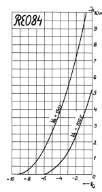
RE084 is limited to max anode voltage of Va=150V
Anode voltage is potential between Anode and cathode only.
For these type of tubes Va should be around 140V or less.
in that region values of -Ug are to about -3V
For about 5-6mA anode current.
So the total input should be less 6Vp-p.
You will have with max signal 4 x 5.65Vp-p=22.6Vp-p with 1:4 input transformer.
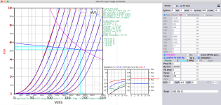
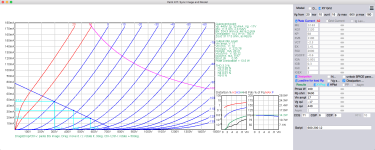
I made Spice model with Bartola mu tracer measurements of RE084 specimen.
Please take a look.
I put 250K as load line of L load or Gyrator emulation.
You have more precise Ri and other datas on the fraph.
There is a spice model too.
.
** BARTOLA MUTRACER MEASUREMENTS ****************************************
* Created on 04/25/2024 13:18 using paint_kit.jar 3.1
* www.dmitrynizh.com/tubeparams_image.htm
* Plate Curves image file: Bartola MuTracer measurements
* Data source link:
* Model fitted by: Zoran
*----------------------------------------------------------------------------------
.SUBCKT RE084 1 2 3 ; Plate Grid Cathode
+ PARAMS: CCG=3P CGP=4.5P CCP=2P
* Only CGP=4.5P is found in the datasheets other capacitances estimated…
+ RGI=2000
+ MU=15.82 KG1=12920 KP=310 KVB=300 VCT=0 EX=2
* Vp_MAX=250 Ip_MAX=10 Vg_step=1 Vg_start=0 Vg_count=10
* Rp=250000 Vg_ac=3 P_max=1 Vg_qui=-3 Vp_qui=140
* X_MIN=99 Y_MIN=34 X_SIZE=602 Y_SIZE=587 FSZ_X=1505 FSZ_Y=729 XYGrid=true
* showLoadLine=y showIp=y isDHT=n isPP=n isAsymPP=n showDissipLimit=y
* showIg1=n gridLevel2=n isInputSnapped=n
* XYProjections=y harmonicPlot=y dissipPlot=y
*----------------------------------------------------------------------------------
E1 7 0 VALUE={V(1,3)/KP*LOG(1+EXP(KP*(1/MU+(VCT+V(2,3))/SQRT(KVB+V(1,3)*V(1,3)))))}
RE1 7 0 1G ; TO AVOID FLOATING NODES
G1 1 3 VALUE={(PWR(V(7),EX)+PWRS(V(7),EX))/KG1}
RCP 1 3 1G ; TO AVOID FLOATING NODES
C1 2 3 {CCG} ; CATHODE-GRID
C2 2 1 {CGP} ; GRID=PLATE
C3 1 3 {CCP} ; CATHODE-PLATE
D3 5 3 DX ; POSITIVE GRID CURRENT
R1 2 5 {RGI} ; POSITIVE GRID CURRENT
.MODEL DX D(IS=1N RS=1 CJO=10PF TT=1N)
.ENDS RE084
*$
Attachments
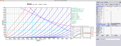
I think that Your RS282 settings are say, wrong
The output power is just 1W.
Tube operate in low voltage and low current region.
There is no point to employ that big tube just for 1W
Ri in that working point is 3.5K
that is huge and needs probably more than 100Hy for primary OT
+
Again very high voltage at the input from input stage.
34Vp-p for that setting is max for not to go into the positive grid bias range...
You will have, again, huge overload to the input of RS282 caused mostly by 1:4 input stepup transfrmer
Should be 1:1
See the RE084 has mju=15.8
RS282 spice models are in zip file
one for DHT composite model other for standard triode
Attachments
Last edited:
Zoran - thank you for the input. Please do me a favor and run the spice model for the RS282 with the following operating points: -18V bias, 610V @ 90mA. I am curious to learn the output of the spice model. Looking at the curves below, this allows us to use the RE084 and input transformer (4*5.6=22Vpp) with minimal overload of the RS282. Not perfect, but getting better. This would swing the RS282 to have ~420Vpp.

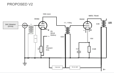
Here is the 2nd version of the schematic (see below) based upon input from everyone.
1. I have some 5K and 1750 ohm 20W resistors to create the voltage divider with a 600V B+. This gives 155R for the driver plate voltage. Is a cap necessary on the voltage divider?
In speaking with Alexander at Muse Coils regarding the interstage tranny, he said that the IT will be fine for my proposed schematic.
The new schematic has the RS282 output tube running at 600V 70ma -18Vbias and a swing of 420Vpp.
Thoughts?
Attachments
HiHere is the 2nd version of the schematic
I will check power tube.
but input section is first issue...
1.
The RE084 cant stand more than Va=150V
In that area -Ug is optimum to be -3 to -3.5V
for Ia=5mA cca.
I will simulate this.
This is important because RE084 is sensitive t exceding max value Ua.
And to keep the total Po less than 1W max
to give the chace to RE084 for longer life.
And still to remain in linear region.
2.
So L load is the goal for higher Amplificaton factor.
In these working conditions RE084 wil output
3.
BUT the tube has huge internal resistance of about 8750 ohms
that deserves minimum 250Hy of inductance to keep the phase shift in LF at acceptable level.
These 110Hy is too low and the guy is wrong when said "it will be OK". How can it tell without calculations and simulation with ral parameters?
.
4.
2Vrms = 5.6568Vp-p
more of digital sources has even more output voltage. Like they comepete to have more and more output inspired of that preamplifiers existing in the system...
With say -Ug = 3.5V that is max half period of input sygnal.
You will have 5.6568 Vp-p / 2 = 2.8284 Vp at the input of RE084. That is safe and under value of -Ug of -3.5V
(with -Ug=3V 2.83 Vp will be too close to the -Ug = 0 in + period...)
WITHOUT 1:4 INPUT TRANSFORMER
thet is good because You will stay in the good range and value of input...
With 1:4 input transformer You will have 4 times bigger value of half period of input 4 x 2.8284 Vp = 11.3V
and that is kill to the -Ug = 3.5V of max input half period...
.
5.
You dont need the 1:4 step up transformer. Cut it out
OR exchange with 1:1 ratio.
But with proper values according to source and from quality...
.
6.
RE084 will export about 92 Vp-p with input of 2.1Vrms.
(But only with L load, Gyrator load and transformer used as L load with high R on secondary in range of 250K like I did it on anode curves diagram for RE084)
Half of that value is mnimum for the -Ug = for RS282 tube
and that is -Ug = 41V
To have more "room" it is better to put -Ug = 45V for RS242 with RE084.
Now You have more proper one factor parameter for setting the RS842.
Withe that, Va of RS242 is a bit more than 900V and for optimizing the tube life
the Ia can be set to 60-70 mA range...
.
7.
110Hy is not enough for Ri = 8750 ohms
Minimum is 250Hy with small capacitance... Which is obtainable...
And these high Ri maybe could not drive RS282 properly?
Maybe You will need some cathode follower...
.
8.
Minimum Lp for the RS282 tube is 80Hy
- Home
- Amplifiers
- Tubes / Valves
- New idea: RE084 drives RS282