Yes and I am not enthusiastic about his choice of metal spacers as the weight-bearing legs. Those can scratch or gouge the surface of the tabletop where the amp rests. I prefer nylon spacers as legs -- or bolting the entire RACAM to a baseplate made of wood or granite (as member @peppennino did on his RACAMs, here ).
I recently purchased the heatsinks from Ali Express seller "KsGrowl LEDs Store" and the mounting holes are slightly different. They are rotated by 90* and the flat sides do not match the flat sides of the PCB. I checked with the seller and the reply I got was, the holes will still fit the LED cxb3590 and the picture might be different from the actual item.
It fits the MOSFETs properly and works well, just the flat side will not be aligned.
Finished building a pair as a gift to my Son.
It fits the MOSFETs properly and works well, just the flat side will not be aligned.
Finished building a pair as a gift to my Son.
Attachments

It might be possible to use 3mm diameter LEDs instead of 5mm, and connect their legs to the PCB through 10mm long, insulated wires. A matchstick shim to fix the LED inside the hole solidly, plus a dab of hot glue, and Bob's your uncle. Scramble-scrunch the excess wirelength, or make it a nice coil, and affix PCB to heatsink. Be sure to trim the LED legs to the shortest possible length, then insulate with heat shrink.
Good day everyone.
Big thanks to designers and developer of this project, fantastic opportunity to enter DIY community.
Purchase a set PCB's for my son to build during his next visit, and can't resist to build one my self.
Work in progress, waiting for Heatsink's and power supply's.
 Best regards.
Sasha.
Big thanks to designers and developer of this project, fantastic opportunity to enter DIY community.
Purchase a set PCB's for my son to build during his next visit, and can't resist to build one my self.
Work in progress, waiting for Heatsink's and power supply's.
Sasha.

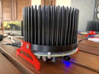
Finally got the bits and pieces. Thought I’d do something a little different for feet and use the ‘flats’ at the side.
Thanks to the two Nelson’s for the awesome ACA and the ‘naked’ look - fits right in as a bedroom setup with the ACP+ 🙃.
And thanks, Mark, for the PCBs that incorporate that cool filter and the generous offer to facilitate ordering. Great triple whammy Class A implementation - ACA, monoblocks and onboard SMPS filter.
Attachments

Finally got my 2nd pair built up after letting a friend have my first ones.
Gone with the 'premium' values and I used a 3.3uf film on the input. Calcutions say it is plenty enough. Interested to hear what the different values bring over and above Nelson's original BOM, although I won't be blind A/B ing and it's been a while since I heard my last set. Also used IRFP140N for both devcies as per my last build as I have a stash of them. Set up and soaking at 24v but the smps will go to nearly 28v so I may see what the temps do and try the higher voltage. Then on to try a trafo and cap bank or even an LT1084. I'd like to try a Tuba built for 24v.
Shame these new heatsinks are 90 degrees out from the originals. I fudged the leds on some flying leads and they're just poked into the holes. Does the job but a bit fiddly.! It also presents the 'flat' with the M4 holes to the front which upsets the aesthetic a bit. Hey ho!
Nice job, Jim. Will be interesting to hear your take on the non-SMPS approach.
Unless I’m mistaken, my hedgehogs were not the ‘original’ units either as the LEDs did not line up with their holes. But by rotating the PCB 90 degrees I got the flats to be on the sides. Only ‘compromise’ was having to use lower profile button-head fasteners to hold down the MOSFETs as the rotation caused the screws to locate close to the edge of the access holes on the PCB and ‘normal’ screws/bolts fouled the PCB. Have a look at my image above for a visual explanation. Or maybe your boards are different, indeed? I also opted to not use the decorative LEDs - mainly out of laziness to fiddle with wires🙂.
Unless I’m mistaken, my hedgehogs were not the ‘original’ units either as the LEDs did not line up with their holes. But by rotating the PCB 90 degrees I got the flats to be on the sides. Only ‘compromise’ was having to use lower profile button-head fasteners to hold down the MOSFETs as the rotation caused the screws to locate close to the edge of the access holes on the PCB and ‘normal’ screws/bolts fouled the PCB. Have a look at my image above for a visual explanation. Or maybe your boards are different, indeed? I also opted to not use the decorative LEDs - mainly out of laziness to fiddle with wires🙂.
Hi Mark, if you are still offering to sell these boards, I am interested in purchase of a set of these RACAM boards. I am a long time reader of DIYAudio forums, but lack enough posts to have a "conversation." However, if you contact me, I can respond with information for an order. I appreciate it.
raynmaine
raynmaine
@raynmaine
Ray,
You might have better luck ordering the entire kit and caboodle right here.
Best,
Anand.
Ray,
You might have better luck ordering the entire kit and caboodle right here.
Best,
Anand.
Attachments
- Home
- Group Buys
- Not exactly a Group Buy: bare boards for RACAM (Round ACA Monoblock)