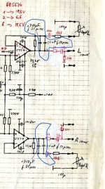
Here is the part of deemphasis circuit of a famous radio. Built around NE5534 output buffer. 33.2K and a choice of a capacitor supposed to form either 50uS (EU) or 75 us(US) time constant deemphasis correction. Currently in the circuit resides 2.2nF combined value of the capacitors and indeed with 33.2kOhm the calculated time constant is around 75uf . The thing is I have no idea how this supposed to work in a feedback loop of an Op-amp . Can somebody sim that circuit? Radio is rolling off the upper frequency like a mofo. By the time we reach 15Khz the amplitude of the signal is at 30% of what the level at 1Khz is. This using FM generator and audio analyzer.
Attachments
Correct .
I took the radio to a friend with FM generator and a scope and he said the passband should look flat after correction is applied. The famous radio sounds like crap and not like $6k tuna. It rolls off mids and highs and wallop with boombox like bass. RF performance is reference class though
I took the radio to a friend with FM generator and a scope and he said the passband should look flat after correction is applied. The famous radio sounds like crap and not like $6k tuna. It rolls off mids and highs and wallop with boombox like bass. RF performance is reference class though
It is an Fm tuner form the "pope of FM tuners "") I just call it a radio. Yes , I did the same calculations and got the same results. Since I lack in theory I just didn't know how the RC positioned in feedback loop of an op-amp will affect the performance because I'm puzzled why it sounds like sh..t although it supposed to be the best in the world
I just call it a radio. Yes , I did the same calculations and got the same results. Since I lack in theory I just didn't know how the RC positioned in feedback loop of an op-amp will affect the performance because I'm puzzled why it sounds like sh..t although it supposed to be the best in the world
I just call it a radio. Yes , I did the same calculations and got the same results. Since I lack in theory I just didn't know how the RC positioned in feedback loop of an op-amp will affect the performance because I'm puzzled why it sounds like sh..t although it supposed to be the best in the worldWell unfortunately it's not only my biased redneck opinion. I sent it out to other Fm aficionado and he said any of his $100 tunas sounds better although he admitted that RF performance was exemplary. So I'm poking around with a screwdriver but nothing looks obviously wrong. I took it to a local friend who has the instrumentation for tuner alignment and he said that it rolls of frequency for whatever reason and because the thing is immensely complicated he advised against touching it
Does the opamp bias correctly at mid-supply? (Some of the bias network is out of view.). Can you confirm that the frequency response of this stage is as expected?
If its frequency response shows the correct 75us rolloff, perhaps there's something wrong in the FM discriminator that's the culprit. Can you and your friend measure response before the de-emphasis stage? Are you able to post more of the FM circuitry?
Good luck.
If its frequency response shows the correct 75us rolloff, perhaps there's something wrong in the FM discriminator that's the culprit. Can you and your friend measure response before the de-emphasis stage? Are you able to post more of the FM circuitry?
Good luck.
You would want to remove the cap; if you shorted the cap, you'd get gain of 1, too little amplitude.I almost have a desire to short that 2.2nf cap to see what kind of impact that circuit has on sound.
Well , the deemphasis circuit seems to be correct after all. I received the response of another owner of this model, who was kind enough to pull it from the shelf ( its not his favorite radio) and compare to Sansui TU- X1. He said he slightly preferred Sansui but it was a toss more or less and he didn't notice any deficiencies in mid- high frequencies as compared to Sansui. Too bad because his example has a much lower standard of components inside meh
- Home
- Design & Build
- Electronic Design
- Opamp EQ circuit help needed