Hello All,@wayne and All,
I have seen the errors of my ways.
Previously while I was setting the series output voltage of the new Keysight bench power supply I entered 19Vrms thinking that in series it would be double that for the + / - series output, it was not. Now the output voltage is corrected to + / - 19 Vrms for a total of 38Vrms. Each 7815 and 7915 on the P3 PCB has volts to regulate 15Vrms + / - at the output of each.
So now The P3 with 4 each 2SK209's functions as expected. Built with Pioneer Kit recommended part values. Thanks to @6L6
Input is 5mv
Gain is 50.39dB
output volts is 1.653Vrms
THD+N is 0.004%
SINAD is 87dB
The above measurements were taken with APx555 analyzer. My expectation is that the limting factor will be the Turntable MM cartridge.
See the updated P3 FFT with 2SK209 Jfets below.
Thanks DT
View attachment 1284978
Today I got around to adjusting the resistance values in the U1A feedback loop.
With the build Document recommended values and J2 jumper in place I got the test results in post #2777.
SINAD is really good and the gain is 50.4dB, too high for my mm cartridge, probably okay if there are no ticks or pops on the vinyl.
Tonight I removed J2 and soldered a 100R resistor where C16 would go. The gain went down by 5dB to 45.36dB and the SINAD went down 16.3dB to 70.7dB. Or THD+N 0.087%
This is good news for the gain and bad news for the SINAD / THD+N.
It looks to me that this P-3 wants to be a moving coil pre-amplifier after all.
Thanks DT
Last edited:
Grounding question.
In the 6L6 online guide, pin 1 of the RIAA chassis power connector is connected to the Neutrik connector tab. Since pin 1 carries power supply chassis voltage (I think), and the tab, RIAA connecter and chassis are uninsulated from each other, this effectively connects the two chassis together.
In the rhthatcher build guide, the RIAA chassis is electrically connected to the turntable binding post, which itself is connected to signal ground. So RIAA chassis is at signal ground. The drawing shows power supply chassis to be unused in the RIAA chassis.
Is there a recommended way?
a) RIAA chassis at power supply chassis ground and not signal ground,
b) RIAA chassis at signal ground and not power supply chassis ground, or
c) RIAA chassis connected to both?
I can see either of the three working. My inclination is to go with a) and insulate the turntable binding post from chassis. Views?
My measured voltages at R27 are way off from each other - one is 2.254v and the other is 1.808v. I imagine these should be more closely matched than that. Before I pick new resistors to get the bias current set properly, where is the next place in the circuit I need to check to remedy that voltage difference?
Typical. This is due to the transfer functions of your two J112 JFET samples not being the same. Trim each R27 individually to get 4 mA across. Or match the J112 JFETs. As these JFETs aren't in the signal path, I did not feel they were worth matching myself, and just trimmed R27s.
Chassis connection for phono is for electrical safety and as shield. Use a four pin connector from the power supply chassis to phono preamp chassis. At phono preamp isolate the audio ground from chassis ground using a 10ohm resistor with 10NF across it, the chassis ground should ground turntable chassis so that you can safely touch it. The cartridges' output is essentially connected to phono preamp using twisted pair, you can even use STP , let the STP jacket earth the turn tableGrounding question.
In the 6L6 online guide, pin 1 of the RIAA chassis power connector is connected to the Neutrik connector tab. Since pin 1 carries power supply chassis voltage (I think), and the tab, RIAA connecter and chassis are uninsulated from each other, this effectively connects the two chassis together.
In the rhthatcher build guide, the RIAA chassis is electrically connected to the turntable binding post, which itself is connected to signal ground. So RIAA chassis is at signal ground. The drawing shows power supply chassis to be unused in the RIAA chassis.
Is there a recommended way?
a) RIAA chassis at power supply chassis ground and not signal ground,
b) RIAA chassis at signal ground and not power supply chassis ground, or
c) RIAA chassis connected to both?
I can see either of the three working. My inclination is to go with a) and insulate the turntable binding post from chassis. Views?
Indeed this makes logical sense. This is what I used in the Paradise phono preamp and it is very quiet, and safe.
What I will do is:
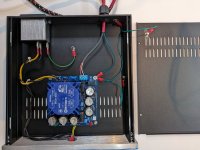
FIY, I use the power PCB from the kit and it provides the necessary bridge connection between power ground and chassis through a metal PCB standoff. The standoff conducts to power supply chassis, which itself has a dedicated ring connector wire to the IEC earth Pin.
What I will do is:
- earth the RIAA chassis through the fourth umbilical wire connected to power supply chassis,
- make the turntable binding post contact the RIAA chassis - exclusively - so it is earth, and
- leave the right and left RIAA PCBs grounds separate, i.e. without connection to the turntable binding post.
FIY, I use the power PCB from the kit and it provides the necessary bridge connection between power ground and chassis through a metal PCB standoff. The standoff conducts to power supply chassis, which itself has a dedicated ring connector wire to the IEC earth Pin.
Just in case some of you had not noticed, the rhthatcher build guide and 6L6 online guide list different connections for the 4-pin umbilical cord. No big deal, just don't mix them.
rhthatcher build guide:
1 ground
2 n/c
3 positive (+)
4 negative (-)
6L6 online guide:
1 jack tab
2 positive (+)
3 ground
4 negative (-)
rhthatcher build guide:
1 ground
2 n/c
3 positive (+)
4 negative (-)
6L6 online guide:
1 jack tab
2 positive (+)
3 ground
4 negative (-)
Version 1.0C of that build guide says:rhthatcher build guide:
1 ground
2 n/c
3 positive (+)
4 negative (-)
No big deal, just don't mix them.
")
Just unpacking kits, ordering chassis and do forth. Looking at bag of actives and resistors first to count and organize.
While counting out actives, checking against BOM, I may be missing something, or may be my misinterpretation of BOM.
Question is on Q1 through Q4, BOM says 8 quantity of 2SK170. On Q10-Q13 Qty 8. The only thing left in the actives bag is a strip of tiny bits, 9.
There is a notation in BOM "stuff only one set of Jfet." I assume, that the tiny strip are the "Only set of Jfets" required, and "Y" next to both 2SK170 BL and 2SK209GR is misnomer?
Otherwise, I guess missing part? So, check schematic for positioning for both, I see Q1-4 listed as 2SK170, but find no Q10-13 which tells me the "stuff only one set" means I am NOT missing anything, right? Or wrong like normal.....which is happening right and left with these things. Back to build guide.
Russellc
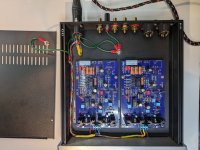
Safety earthing photos for the scheme given in post #3146. Everything connected by green wires is tied to IEC safety earth. My umbilical carries earth on pin 1, and is not shielded.
All that is left is connecting the RCAs and XLRs, and testing.
By the way I confirm that there is very poor or no conductivity between the six enclosure sides - as pointed out in 6L6's guide. Especially the powder coated steel cover and bottom: the paint is very durable . Scratching the sides did nothing. A Dremel tool proved handy for removing paint on the cover and bottom around earthing holes, and for scratching the inside of the anodized front panel's corner holes for the socket head bolts. These bolts can then electrically connect the front panel to the sides - and the sides together. Wires and ring terminals connect cover, bottom, front+sides, and rear panel. I have not decided if it is worthwhile to earth the XLR cases
All that is left is connecting the RCAs and XLRs, and testing.
By the way I confirm that there is very poor or no conductivity between the six enclosure sides - as pointed out in 6L6's guide. Especially the powder coated steel cover and bottom: the paint is very durable
. Scratching the sides did nothing. A Dremel tool proved handy for removing paint on the cover and bottom around earthing holes, and for scratching the inside of the anodized front panel's corner holes for the socket head bolts. These bolts can then electrically connect the front panel to the sides - and the sides together. Wires and ring terminals connect cover, bottom, front+sides, and rear panel. I have not decided if it is worthwhile to earth the XLR casesAttachments
I was thrown by Y in the included box...
...Yeah, I understand your confusion, looking at that page it's less clear than it should be. Will make some corrections.
And to verify, there's (9) included 2SK209GR in the kit. (An extra is included in case you sneeze...) And there is no Q10-Q13, even though there's double pads for the Jfets.
Use the K209s, be happy.
Besides Pearl 3, I just finished Iron Pre and XA252, as well as X's XSD speaker. I'm half way through another DCG3 build, starting another of X's speakers and this F5m kit is staring me in face. Yes, they are beginning to blur and my living room floor and dining room table have been out of commission for a while. Confusion abounds.
Time for a break!
Time for a break!
Use the K209s, be happy.
that's so straightforward and boring, besides - preventing Regular Greedy Boy of having proper feeling of personal search for Holly Grail

- Home
- Amplifiers
- Pass Labs
- Pearl 3 Burning Amp 2023