MiJust to let you know that there are 10 more Emerald PCBs available, which I can send out to Europe countries which can't be posted by RJM via air mail only. I forgot to clear my basket on my last order of PCB's from my provider in China that's why they are on stock now. 12€ a pair including shipping to Germany only. Other Europe countries 10€ a pair plus shipping.
I would love to order a pair of boards if you still have some. Greatings, Jurjen from the Netherlands
I did send you a private message @Jurjen1965 - ok fun fact I will be in Japan for 2 weeks from tomorrow on ;-)
Hi All,
I am prepping supplies to build an Emerald and am wondering whether it would be possible to use the DIY Power Supply Unit from AkitikA to power the phono boards. I have included a photo and specs below from the AkitikA website. I previously built an AkitiKa GT-102 amp that I really like, so figured that the PSU would be a good foundation for projects. But once I started looking at the details I am second-guessing the compatibility here. Thank you.
--==--==--==--==
Specifications:
- +12 volt output
- tolerance: worst case +/- 0.5 Volts, typically +/-0.25 Volts or less
- nominal output capability: 200 mA
- output current: 100 mA produces 17.5 C temperature rise in the heatsink
- -12 volt output
- tolerance: worst case +/- 0.5 Volts, typically +/-0.25 Volts or less
- nominal output capability: 200 mA
- output current: 100 mA produces 17.5 C temperature rise in the heatsink
- +5 volt output
- tolerance: worst case +/- 0.25 Volts, typically +/-0.125 Volts or less
- nominal output capability: 750 mA
- output current: 100 mA produces 12 C temperature rise in the heatsink (note that temperature rise is slower than linear for output currents above 100 mA)
Attachments

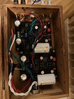
Follow up on my Emerald build. I ended up ordering a power supply kit from RJM rather than using the AkitikA PSU. Decided to house the power supply and phono stage in separate wooden dresser boxes. Found a box that was a great size for the power supply - see photos. The box with phono stage is a bit cramped - in hindsight it would have been a little easier in a larger enclosure as Richard has noted in several posts. I have been playing records for the past few days so still burning in my Emerald. But the sound is already a noticeable step up from the entry level phono stage that I had been using.
The next phase of the project will be to do some RF/EMI reducing. Any tips are appreciated. As you can see in the photos my turntable is an old Kenwood that could definitely use updated RCA cabling as they are brittle. I am also planning on getting some EMI/RF absorption material and experimenting with placement in the phono stage.
Thanks again to Richard for making this project available.
Attachments
@doug_fur
As lovely as it looks - and it sure does look pretty - wooden boxes, or any non-conductive enclosures, are not ideal for housing sensitive electronics. And a MC phono preamp is about as sensitive a circuit as you get in audio.
So yeah, your Emerald is essentially "naked", exposed to any and all airborne electrical interference.
To get a quiet signal, at the very least the Emerald circuit must be fully surrounded by a metal enclosure connected to the circuit GND. Sometimes additional measures may be needed to counter RFI, but that's the first step.
You can think about re-casing your phono stage or adding a metal inner case to the wooden boxes you currently use. Remember though that it isn't enough to just add metal. The metal parts must be electrically connected to the circuit ground or, for the power supply, earth.
Thanks Richard. Good to know. I am running an MM cart right now but definitely plan on moving to MC soon. I have a Hammond 1590F box so will start with moving the phono circuit into there, which shouldn't take too much effort. For the PSU I did mount a steel plate onto the bottom of the box and attached ground lug to it, which is hopefully sufficient if not ideal.
Quick update on the wooden box RF/EMI situation. A friend suggested that I try lining the boxes with copper foil, which seems to have helped immensely and was fairly low effort although I did remove the boards and hardware so that I could get thorough coverage with the foil.
Thanks again for the help. Really enjoyed the project and it's sounding great.
Thanks again for the help. Really enjoyed the project and it's sounding great.
Glad it worked out. Copper lining will do the trick, though there is a bit of a long-term issue in the electrical contact between the copper sheets degrading over time as the metal oxidizes. Think of it as using the foil to build a case ... if you can use fasteners, stables, or screws of some kind to join everything together. Metal by itself isn't a screen ... the metal must be in electrical contact with the circuit GND.
Fasteners to join should be copper nails as any other metal will accelerate corrosion.
https://www.corrosionpedia.com/why-do-two-dissimilar-metals-cause-corrosion/2/6678
Some years ago we used Cramolin Blue to protect and seal connections from oxidation. (Red was the cleaner and Blue the protector)
https://www.conrad.com/p/cramolin-contaclean-1011611-electrical-contact-cleaner-400-ml-820531#!

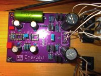
I would like to ask for a little help. I built the emerald, but unfortunately, when I turned it on, I found that the mains transformer (50VA 2x12V 1.6A) was hot and I measured only 0.6 V at the power supply connections of both circuits. When I removed the circuit from the rectifiers, I measured 14 V. I tried to start only one channel from another 20VA 12V transformer, but unfortunately I measured the same value. What do you think I messed up? I am also attaching a photo of the board model.
Attachments
@atreides
As @ranshdow helpfully pointed out, it's clearly a connection issue and somehow you've shorted one or more of the secondary windings through a diode, hence the 0.6 V reading. It's hard to see from the photo what the connection scheme is, and we don't know the arrangement of the transformer windings, so I can't tell you exactly what you did wrong. However, diodes are wired incorrectly, that's certain.
You don't need to use four bridge rectifiers, and you can only use four if you have two separate power transformers, one for each channel.
For the Emerald you normally only have one power transformer. You can connect with just a single bridge rectifier in the usual way splitting the output to each board, or you can use two bridge rectifiers as shown in the construction guide. Personally I'd just use one if I was building today, I originally used and suggested two because it's a more foolproof connection scheme for beginners to deal with. (Since you don't need to have to identify the phase of the secondaries to make the correct connection.)
@atreides
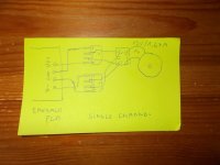
You can't use a single secondary winding to generate both the positive and negative voltage rails. You need to replace your transformer with a model that has two secondary windings, or use a second transformer of the same kind as you are using now to connect to the second diode bridge:

You can't use a single secondary winding to generate both the positive and negative voltage rails. You need to replace your transformer with a model that has two secondary windings, or use a second transformer of the same kind as you are using now to connect to the second diode bridge:
rjm
Yes, the original transformer which I had ordered is 50VA 2x12V secondary. Now it isn't hot. I measured the supply voltage on the pins of the ICs, but unfortunately I measured -9.13 V and +17.5 V on one panel, while -12.4 V and +13.8 V on the other. What could this be? ?
Yes, the original transformer which I had ordered is 50VA 2x12V secondary. Now it isn't hot. I measured the supply voltage on the pins of the ICs, but unfortunately I measured -9.13 V and +17.5 V on one panel, while -12.4 V and +13.8 V on the other. What could this be? ?
- Home
- Source & Line
- Analogue Source
- RJM Audio Emerald Phono Stage Help Desk