SE-100 Golden Tube Audio - REPAIR
I need some help and good advice on repairing my 100 watt tube amp.
I plan on replacing two burnt looking, but measuring well (when cold and off) resistors located near my tubes. I don't know if they are acting up once they warm up, but they are scary looking. However, this thread is not dedicated to that issue, just disclosing all the variables I can up front.
I really have not used the amp much in the past year, maybe once a month. Two years ago, after a tube failed and charred a couple of resistors (already mentioned), an annoying problem showed up. About 5 minutes after turn on a high pitched squeak which lasts about 1.5 seconds comes out of the speakers. I learned to keep the preamp off until after the squeak to minimize the volume and intensity. This was an intermittent problem and did not happen every time, may half the time.
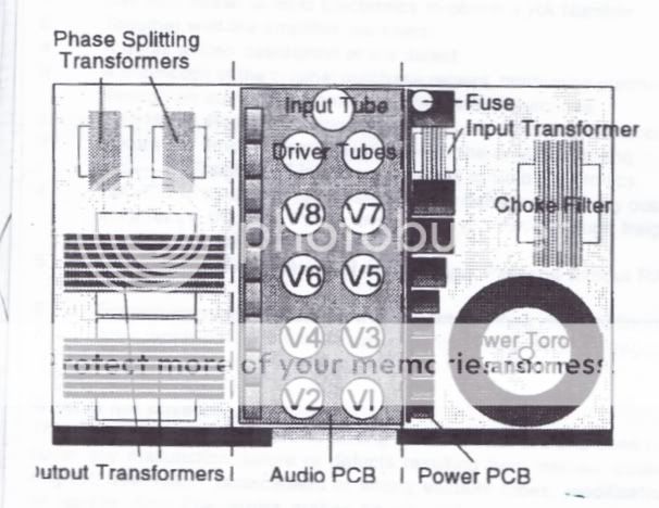
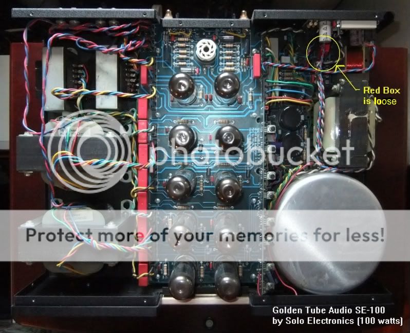
The amp stopped working last week (power light comes on and all the tubes (125 hours) glow), I've opened it up and checked the fuse, and for loose connections and more burnt items. All I found was this wobbly and loose RED BOX.
I have no wiring or circuit diagrams for my amp, and the owner's manual is for a similar amp, but not my model of this amp.
1. What is this Red Box?
2. How should it be attached?
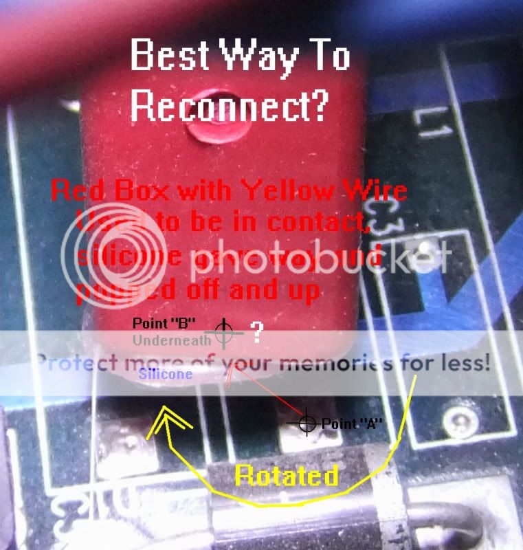
3. Is there really a contact point underneath, or is the silicone isolating it?
4. What is the best way to restore the mounting?
A picture is worth a thousand words, so here they are:
Stereo pictures by kach22i - Photobucket
Money is tight, so I'd rather do these repairs myself. I can solder a little (know you can heat it up too little, or too much), have silver solder, an iron, and a solder sucker just in case.
I need some help and good advice on repairing my 100 watt tube amp.
I plan on replacing two burnt looking, but measuring well (when cold and off) resistors located near my tubes. I don't know if they are acting up once they warm up, but they are scary looking. However, this thread is not dedicated to that issue, just disclosing all the variables I can up front.
I really have not used the amp much in the past year, maybe once a month. Two years ago, after a tube failed and charred a couple of resistors (already mentioned), an annoying problem showed up. About 5 minutes after turn on a high pitched squeak which lasts about 1.5 seconds comes out of the speakers. I learned to keep the preamp off until after the squeak to minimize the volume and intensity. This was an intermittent problem and did not happen every time, may half the time.
The amp stopped working last week (power light comes on and all the tubes (125 hours) glow), I've opened it up and checked the fuse, and for loose connections and more burnt items. All I found was this wobbly and loose RED BOX.
I have no wiring or circuit diagrams for my amp, and the owner's manual is for a similar amp, but not my model of this amp.
1. What is this Red Box?
2. How should it be attached?
3. Is there really a contact point underneath, or is the silicone isolating it?
4. What is the best way to restore the mounting?
A picture is worth a thousand words, so here they are:
Stereo pictures by kach22i - Photobucket
Money is tight, so I'd rather do these repairs myself. I can solder a little (know you can heat it up too little, or too much), have silver solder, an iron, and a solder sucker just in case.
Last edited:
Red box looks like a relay to me, maybe for speaker outputs or input power or? I see some power diodes and caps on the same board with it so maybe more likely something power related, maybe powers a particular section of the amp. Any printing / diagrams on it?
There is a Yahoo forum for Golden Tube Audio of which I am a member (although I do not own any of their products). Try joining and asking there.
Lots of info available.
Get regular solder and do not mix / use silver solder on this amp, you can buy leaded solder in a small tube. Radio Shack used to carry regular lead solder but not sure if they have phased it out now.
Not sure if you are aware but the Golden tube products and in particular the se-40 and se-100 have reputations as being VERY unreliable but with a lot of effort can be made better.
I have always liked the SE-100's looks and being the glutton for punishment that I am I would probably buy one 😱
Andrew
Last edited:

Kach22i,
I see where you have already posted the same question in the Yahoo Golden tubes forum so you are already a member. Look in the files section and you will find the se-100 schematic.
I see where you have already posted the same question in the Yahoo Golden tubes forum so you are already a member. Look in the files section and you will find the se-100 schematic.
I've looked for years for a schematic, but need to double check, as it's been a couple of years since the last time I checked. My model is different than the Asian, European or some other models with the same SE-100 designation.Look in the files section and you will find the se-100 schematic.
Just an FYI and for future reference, one of the other Golden Tube Audio Yahoo Group members wrote back to me. I consider him an expert on these things, and he has been willing to coach me on GTA ownership for several years now.
George,
As i said i am not familiar with the layout in your version of the amp.
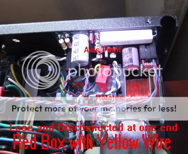
The "red box" looks like a single capacitor located in the power input / ac filtering stage of the amp.
It should be a Wima capacitor with high voltage tolerance...
You have to solder the lifted end back to it's soldering point to reestablish the connection.
The best way to do this is to take out the relative board and do the soldering from the back side.
If this too much for you you, will have to cut a small piece of wire and solder one end to the caps' lead and the other to the board contact point...
You can check the input connection of the signal with a modest DVM using the continuity test placing one probe in the plus and minus points of the input jack and the other on the relative traces on the input board that is located on the rear of the tube board.
Keep me posted.
Ioannis
As far as amp reliability, the SE-100 is supposed to be the beast of the lot, with the SE-40 and 300B being much more temperamental.
My problems for the most part have been self inflicted, by biasing old tubes to 500mv in lieu of a safer 450mv (I followed what was in writing). This is how I fried or at least charred the outside casing of two resistors.
My current problem I attribute to age, that dab of silicone or glue just was not going to last forever. Perhaps the designers could have made it to last forever, but I'm sure it would not have been the value amp it was in it's day if that were to pass.
I'd love to pick up a second matching amp, as these have a switch on the back for mono bridging.
Get regular solder and do not mix / use silver solder on this amp, you can buy leaded solder in a small tube. Radio Shack used to carry regular lead solder but not sure if they have phased it out now.
I have some leaded solder somewhere, I'll find it. I recall it being much ticker than the thin silver Cardas solder I found in my box.
Last edited:
I like this short-cut method from the Yahoo Group even better.
The loose red box is not an issue...............
1) The red box is called Wima capacitor (cap). You have another 8 of them on the left side of Main Board (MB) and
two smaller ones at the rear. They are all coupling caps on the MB. It has 2 pins/leads. One pin was broken off. When a cap or resistor has one pin open, it is considered not in the circuit, not used, open.
2) The red box in question (on the PS board) is not used as a coupling cap, but as a filter across the power switch to dampen sparks when the power sw is turned on. It is not needed, I removed it on my unit. It is very labor extensive to
un-solder the remaining pin, unless you can gently rotate it and remove it.
3) Use a tape on the board to prevent the broken part/pin can make contact with other nearby metal points.
Use another tape to keep it in place, if you can not remove it as described above
Good luck
Loc
Kach22i
I am also a GTA Se-100 owner from Michigan and have burned a resistor (r27). I was hoping you knew what the value of this resistor is? I have checked the schematic that I have and it does not make sense. I am assuming that r28 uses the same resistor and that is a 10 ohm. Could you possibly check your sources or maybe measure the value on your amp? Any help would be greatly appreciated.
Thanks,
Arnie
Se-100 capacitor remounting
Hello,
I am in the process of rebuilding my Se-100 and drawing the schematic by hand so that I can work on it. What a fun project anyway.....
That red box is a brand name “Wima” capacitor. Solo electronics should have done a better job of mounting it. Mine was glued to the circuit board. It came loose so I put a good quality smaller capacitor in its place. That worked well. It functions as an ac filter cap. for the input 120 vac that’s why it is near the IEC ac plug.
If you have a broken wire you will have to remove the high voltage power supply board and resolder the lead or leads into circuit board. It is a non-polarized cap so that’s pretty straightforward. If no leads are broken it can be remounted with a small amount silicone glue. Silicone is what Solo electronics used to secure it.
Let me know what you find?
Tuber1956.......Dennis
- Status
- Not open for further replies.
- Home
- Amplifiers
- Tubes / Valves
- SE-100 Golden Tube Audio - REPAIR