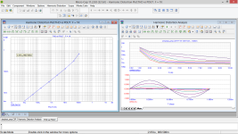
I suggest you download LTC Spice and simulate your circuit.
You will find that there is a great deal of DC current in the speaker which will quickly burn it out and will make the speaker diaphragm pop in or out. If we ignore that undesirable DC speaker current, the bias resistor should be roughly the load resistance times the transistor gain, ie about 100 x 6 = 600 Ohms. This is a very crude circuit for educational purposes, but it is not good enough for actual use long term. You should search these web pages for simple "headphone amplifiers" which are also very simple but good enough to be actually useful.
You will find that there is a great deal of DC current in the speaker which will quickly burn it out and will make the speaker diaphragm pop in or out. If we ignore that undesirable DC speaker current, the bias resistor should be roughly the load resistance times the transistor gain, ie about 100 x 6 = 600 Ohms. This is a very crude circuit for educational purposes, but it is not good enough for actual use long term. You should search these web pages for simple "headphone amplifiers" which are also very simple but good enough to be actually useful.
A transistor used like that without emitter degeneration is about as distorted as you can get, as it has an exponential relationship between output current and input voltage. But it is probably the very first transistor amplifier ever made, it has a place in history!
The reason you don't want any DC in the loudspeaker is it will cause the voice-coil to push against the coil endstops, or the spider, buzzing there rather than vibrating about the neutral mechanical suspension point.
The reason you don't want any DC in the loudspeaker is it will cause the voice-coil to push against the coil endstops, or the spider, buzzing there rather than vibrating about the neutral mechanical suspension point.
I used to build these when I was a kid. My father gave me a car battery that he had put "taps" into, so I could select the voltage in 2V increments up to 12. I remember the voice coil pulling back due to quiescent current flow. I remember how - even then - I thought it sounded better with the VC pulled back like that. Certainly sounded different. Was probably driven by a crystal radio set...
My curiosity piqued when I discovered General Motors car radios used this transformer looking device along with the big transistor, which apparently "fixed" the current issue - or made it a lot less. That output stage seemed to be replicated across a number of car radio examples, including one I found dumped behind a service shop that was stereo. That device was an autotransformer, basically a coil with a tap to feed the speaker,
This was probably around 1970. If I had a shred of tenacity and stick-tuitiveness, I could have been the king of class A. Instead, I bought a SWTPC "lil Tiger" amp and never looked back, as of course 20W of complimentary-symmetry beat the hell out of the stupid single transistor few Watt "car radio" amp. Or so I was as suitably impressed at the time.
https://deramp.com/swtpc.com/PopularElectronics/Dec1967/PE_Dec1967.htm
I was playing around with inverters then too and miraculously managed to successfully substitute transistors for a mechanical vibrator (by looking at a multivibrator schematic), which gave me 100+ VAC from 12V DC. Again, I was skirting an opportunity to solve the high power car stereo issue at the time - which no one had - but due to my untenacious nature I never bothered to fool around further with the transformer and its windings, to make, say, +45V DC instead for the tiger amp. I kinda regret that, even though I ended up doing automated power supply test for most of my career. I could test 'em - not design them.
Be encouraged to explore your little circuit, particularly in the area of refinement. Take it as far as you can in only for your own learning and experience, before jumping into "oh this other one is so much better". There's a 1000 ways to fry the audio amplification-egg and you can get overwhelmed easily swimming through the myriad of choices.
Last edited:
Hello, I'm a student in major electronics. I've learnt about amplifier already. I want to ask my circuit design below is correct or not, and are there any problems? Thanks for helping.
Make it this way:

This will work. Put BD139 on some heatsink.
P.S.: I sincerely hope your post #1 is a good joke 🙂.
Last edited:
When I was fooling around with the likes of post #1 circuit, I'd have wished someone could show me your "make it this way". I would have learned a lot -P.S.: I sincerely hope your post #1 is a good joke 🙂.
What transistors do you have?Hello, I'm a student in major electronics. I've learnt about amplifier already. I want to ask my circuit design below is correct or not, and are there any problems? Thanks for helping.
So, the OP has disappeared and all the fun is left for us?? 🙂
I built the circuit from my stock components, with some small changes, due to my stock. Input pot was omitted.


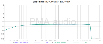
THD and THD+N at 1kHz, 0.5Vrms and 10ohm load

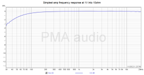
Frequency response THD vs. freq
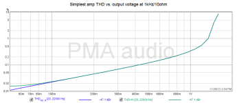
THD vs. level at 1kHz/1V
We could compete to NP with this 😛.
If pot is needed, it should 1k, or 5k max., with linear taper.
To prevent any confusion, R3 (10ohm) represents the speaker in the schematics. If the speaker is used, R3 must be omitted,
I built the circuit from my stock components, with some small changes, due to my stock. Input pot was omitted.
THD and THD+N at 1kHz, 0.5Vrms and 10ohm load
Frequency response
 THD vs. freq
THD vs. level at 1kHz/1V

We could compete to NP with this 😛.
If pot is needed, it should 1k, or 5k max., with linear taper.
To prevent any confusion, R3 (10ohm) represents the speaker in the schematics. If the speaker is used, R3 must be omitted,
Last edited:
thanks for your adviceI suggest you download LTC Spice and simulate your circuit.
You will find that there is a great deal of DC current in the speaker which will quickly burn it out and will make the speaker diaphragm pop in or out. If we ignore that undesirable DC speaker current, the bias resistor should be roughly the load resistance times the transistor gain, ie about 100 x 6 = 600 Ohms. This is a very crude circuit for educational purposes, but it is not good enough for actual use long term. You should search these web pages for simple "headphone amplifiers" which are also very simple but good enough to be actually useful.
Sorry everyone for disappearing for a long time. Hope that I don't miss too much useful advice you gave. Because I live in different time zone (Vietnam) and I don't have much time to check noti on the internet. Anyway thankyou for your advice
It'll be a photo finish with the emitter and collector pins accidentally swapped, assuming there was a distinction in the early days.But it is probably the very first transistor amplifier ever made, it has a place in history!
If I don't have AC voltage source, how will the circuit change or there is sth to replace?Make it this way:
View attachment 1239559
View attachment 1239565
This will work. Put BD139 on some heatsink.
P.S.: I sincerely hope your post #1 is a good joke 🙂.
Instead of AC voltage source you use analog output of CD player, soundcard or mp3 player or any other source with analog output. It may be headphone output quite well. AC source is for simulation purposes. For measurements, soundcard output was used. You will make no changes in the circuit. You may use your 2SD718, it will work same as my 2SC5200.
Look, you should start to study the absolute basics, basics of reading schematics. I have already explained that the speaker is connected instead of R3, at the same place. R3 = speaker. You also have a photo. You said you are a student of electronics, but I do not think so.

P.S.: I have connected this "amplifier" to the small 2-way speaker, and the sound is absolutely normal, as long as we stay inside its power capabilities. Enough for desktop listening from PC.
P.S.: I have connected this "amplifier" to the small 2-way speaker, and the sound is absolutely normal, as long as we stay inside its power capabilities. Enough for desktop listening from PC.
- Home
- Design & Build
- Electronic Design
- Simple amplifier circuit

