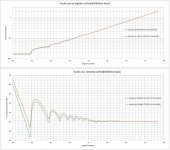
A few months ago, @gpapag posted up some linearity plots of a couple of experimental 'Abbado' DACs I'd sent him. Below around -66dB (equivalent to the 11th bit), the results begin to look not too great, certainly not in comparison with DACs based on much more modern S-D chips which tend to have near-perfect performance on this particular metric. I played around with making some low-level measurements myself and confirmed the basic premise that low-level linearity is an issue and from varying the input levels t looked to be due to inaccurate bit-weightings in the DAC's internal architecture. What I didn't know though was how big of a bit-weight error is needed to give rise to such deviations from linearity - I wanted to get a handle on the order of magnitude involved. I figured maybe I could coax LTSpice into doing some simulations of this.
LTSpice allows input of .wav files to the sim, the data is converted to analog automatically before being applied to the circuit. What I really needed in order to test out DAC linearity was the ability to input digital data, not analog. As far as I'm aware that's not an available feature so I wondered if I could develop an ADC which would convert the .wav file back to digital in the simulation and then I could apply that digital stream to my simulated DAC. By tweaking the bit weights in the simulated DAC I might be able to see how linearity is affected and get a feel for the degree of effect. But how to design an ADC?
There are two kinds of ADC which might be suited to this task - a 'flash' and an 'SAR' type. The flash type has the disadvantage of complexity - it needs of the order of 2^N comparators for an N-bit ADC. I figured I'd want to begin with a 5 or 6 bit ADC and to save on a lot of copy pasting to create a flash ADC I wondered if the SAR type might be better suited. An SAR ADC only needs a single comparator but has a significant disadvantage of needing a clock and a register to remember the results of earlier comparisons. I've never built any clocked logic circuit before in LTS and, being very lazy I decided to at least try to combine the clock-free nature of the flash converter with the low component count of the SAR. Perhaps I'll call my approach the 'FA' for 'flash approximation' - it falls between the two in complexity, only using one comparator for each bit. It needed a little bit of tweaking to create what appeared to be a working 6 bit ADC out of 12 voltage controlled switches and 6 reference voltages - being as the switch type in LTSpice is a single pole and I wanted a changeover function I wired two single pole switches in anti-phase. Of course such a design would never work in the real world but that doesn't matter in this instance, its only going to live inside the sim. Being as it produced a nice stepped waveform for an input sinewave with very little effort I began to be suspicious if there wasn't some hidden gotcha going to bite me further on down the road. So I needed to characterize my 6 bit FA ADC to ensure such a simple design really delivered the goods.
To characterize it it needs to drive a DAC back to back and then I can do tests on the DAC's output waveform. The DAC is almost the same as the ADC and uses 12 voltage controlled switches and again 6 voltage references (but different instances) for the bit weights. I hooked up a sinewave voltage source at full-scale into the input and ran an FFT on the DAC's output. Looked respectable indeed and the SFDR was in the region of -60dB, too good to be true! I took the input amplitude down to 2LSBs (about 30mV) and wondered what would show up. Quantization distortion, that's what. Ah, dither would come to the rescue I thought. I had to delve into the workings of LTSpice for this as I'd never created an explicit noise source before - the 'White' function serves a good purpose. TPDF dither (needing two uncorrelated sources summed) would have to wait as just creating two instances of 'White' can't uncorrelate them. How to set the dither amplitude? I figured do it by eye when the FFT completely lost the spurs of the harmonics of the test tone. The 'White' function also has a parameter which seems to relate to the bandwidth of the noise generated, I got decent enough results setting this to 44,100. But I couldn't resist high-passing the output before applying it in series with the test tone.
So now I had what appeared to be a kosher ADC feeding a perfect DAC and at least based on FFTs, the results were as close to textbook as I could have hoped. Time came to try making some linearity measurements - I figured to get the best measurements of amplitude I'd want a low-pass filter do get as clean signal as possible, so I plugged a 1kHz 5th order Chebyshev lowpass on the output of the DAC, the stimulus being 1kHz. Using the 'step' feature I ran a sequence of different levels into the ADC and made '.meas' of the output. Still being a bit suspicious of my ADC though I also put the amplitude quantized analog version of its own digital output through another instance of the same filter and compared. The ADC line wasn't straight at lower levels, it had a bulge. Hmm, what could cause this?
<attached George's linearity plot of the prototype Abbado DACs which use TDA1387>
Attachments
Last edited: