Or, for winding the core, if you are not good at math, you can place a light bulb in series with the power input to the circuit or the transformer as Eva suggested, and add turns to the primary until it can idle without anything heating up.
Bean Z and Claude Abraham, is there something about this area of Ohio where we just seem to be interested in SMPS design? I can't send an email because my browser is dysfunctional. You can reply that way if you feel like saying "Hi".
Bean Z and Claude Abraham, is there something about this area of Ohio where we just seem to be interested in SMPS design? I can't send an email because my browser is dysfunctional. You can reply that way if you feel like saying "Hi".
Bean Z and Claude Abraham, is there something about this area of Ohio where we just seem to be interested in SMPS design? I can't send an email because my browser is dysfunctional. You can reply that way if you feel like saying "Hi". [/B]
You have "Boss Kettering" on the Brain
") , at least those of you from the Dayton area.
, at least those of you from the Dayton area.and how's about those 15 foot swells on Lake Erie? That's what sunk the Edmund Fitzgerald!
jackinnj said:
and how's about those 15 foot swells on Lake Erie? That's what sunk the Edmund Fitzgerald!
That makes three others now.
That area must be in the Great Lakes Triangle.
Just thought of something, though, I don't think email will work either because of anti-spam filters.
NE Ohio & SMPS design
Well, my interest in SMPS design is necessary as I earn my living designing electronic products. The input power source I've designed around over the last 25 years has been the 12 and/or 24 volt automotive bus, 115 and/or 230 volt 50/60 Hz commercial power, 28 volt military bus, full-wave-rectified 12 & 24 volts ac, and batteries. Output voltages range from 1.8 volts to 450 volts. With an SMPS, the options are numerous. One can convert an input to just about any value of output with high efficiency and small size, especially in ac offline applications where 50/60 Hz transformers used in non-SMPS are large and heavy. In addition, I happen to have a personal fascination with SMPS, including design of the custom magnetics. With SMPS design, virtually every aspect of EE comes into play. Analog circuits, digital logic, magnetics, e/m fields, automatic control loops, feedback & stability, math, component parameters & limitations, rf & emi filtering, all come into play with SMPS design. I am basically a nerd. I really enjoy this stuff.
Bean Z and Claude Abraham, is there something about this area of Ohio where we just seem to be interested in SMPS design? I can't send an email because my browser is dysfunctional. You can reply that way if you feel like saying "Hi".
Well, my interest in SMPS design is necessary as I earn my living designing electronic products. The input power source I've designed around over the last 25 years has been the 12 and/or 24 volt automotive bus, 115 and/or 230 volt 50/60 Hz commercial power, 28 volt military bus, full-wave-rectified 12 & 24 volts ac, and batteries. Output voltages range from 1.8 volts to 450 volts. With an SMPS, the options are numerous. One can convert an input to just about any value of output with high efficiency and small size, especially in ac offline applications where 50/60 Hz transformers used in non-SMPS are large and heavy. In addition, I happen to have a personal fascination with SMPS, including design of the custom magnetics. With SMPS design, virtually every aspect of EE comes into play. Analog circuits, digital logic, magnetics, e/m fields, automatic control loops, feedback & stability, math, component parameters & limitations, rf & emi filtering, all come into play with SMPS design. I am basically a nerd. I really enjoy this stuff.
Re: NE Ohio & SMPS design
This advantage is my main motivation.
Claude Abraham said:
One can convert an input to just about any value of output with high efficiency and small size, especially in ac offline applications where 50/60 Hz transformers used in non-SMPS are large and heavy
This advantage is my main motivation.
Re: NE Ohio & SMPS design
I am disappointed that neither of you guys got the reference to Kettering -- the inventor of all the electronics which went into GM vehicles from the '20s I believe -- his life story is as worthy reading as Alfred P. Sloane's "My Years with General Motors", and he was from Ohio.
Claude Abraham said:One can convert an input to just about any value of output with high efficiency and small size, especially in ac offline applications where 50/60 Hz transformers used in non-SMPS are large and heavy. In addition, I happen to have a personal fascination with SMPS, including design of the custom magnetics. With SMPS design, virtually every aspect of EE comes into play. Analog circuits, digital logic, magnetics, e/m fields, automatic control loops, feedback & stability, math, component parameters & limitations, rf & emi filtering, all come into play with SMPS design. I am basically a nerd. I really enjoy this stuff.
I am disappointed that neither of you guys got the reference to Kettering -- the inventor of all the electronics which went into GM vehicles from the '20s I believe -- his life story is as worthy reading as Alfred P. Sloane's "My Years with General Motors", and he was from Ohio.
Re: Re: NE Ohio & SMPS design
Sorry, I thought the knowledge was presupposed on your part. Kettering was the inventor of the electric automobile starter at that.
jackinnj said:
I am disappointed that neither of you guys got the reference to Kettering -- the inventor of all the electronics which went into GM vehicles from the '20s I believe -- his life story is as worthy reading as Alfred P. Sloane's "My Years with General Motors", and he was from Ohio.
Sorry, I thought the knowledge was presupposed on your part. Kettering was the inventor of the electric automobile starter at that.
Kettering, OH? Hmmmm
Interesting. I just moved to Kettering just a few months ago after living all my life in Des Moines, IA. Number of reasons for that including all the great industrialization history around here. Plus, wow - the locals know and love electronics. It's simply amazing.
I've attempted ONE offline powered SMPS, and needless to say I didn't have enough time to complete it - or actually make it work properly. I would enjoy learning offline SMPS in more detail.
I'm no math wiz by any means, but I'm capable and willing to learn - I guess I'm just intuitive about this stuff so I stick with it.
I'd love to hear from other Dayton area folks about SMPS. Maybe we can start a little club or something...
Regards,
Aaron Hammett
aaron@envisionelectronics.com
Interesting. I just moved to Kettering just a few months ago after living all my life in Des Moines, IA. Number of reasons for that including all the great industrialization history around here. Plus, wow - the locals know and love electronics. It's simply amazing.
I've attempted ONE offline powered SMPS, and needless to say I didn't have enough time to complete it - or actually make it work properly.
I would enjoy learning offline SMPS in more detail. I'm no math wiz by any means, but I'm capable and willing to learn - I guess I'm just intuitive about this stuff so I stick with it.
I'd love to hear from other Dayton area folks about SMPS. Maybe we can start a little club or something...
Regards,
Aaron Hammett
aaron@envisionelectronics.com
an OFFLINE Smps is daunting -- I started making flyback converters with the LM3524D about 6 years ago, then used the Nat Semi Simple Switchers for buck, boost and inverting, and now tinkering around with very low noise push-pull -- the idea being to get microvolts of noise instead of the millivolts -- just got in a bunch of LT3439's from Linear today along with LT1964's, LT1761's -- I will go blind soldering these thin-SOT devices (actually "toaster oven reflow" !) So we are straying a bit from car-audio since the ambient noise levels in the car and tens of decibels different from those in my den.
There is a well thought-out design in the ARRL handbook with details on winding the transformers. Perplexingly they use bipolar switching transistors AND the LM3524 (which isn't a current-control chip.)
The HamVention is staying in Dayton, btw.
There is a well thought-out design in the ARRL handbook with details on winding the transformers. Perplexingly they use bipolar switching transistors AND the LM3524 (which isn't a current-control chip.)
The HamVention is staying in Dayton, btw.
I also make my living designing electronic products. Most of which are custom high reliability aerospace application products. I, myself, am primarily an analog / power engineer. I have designed a few switchers including a ZVS and an active power factor correction front end with universal input. If anyone has any questions about switchers or wants some incite or questions you can email me at BeanZAudio@columbus.rr.com. I will try to help as much as I can. Just bear be patient for a reply.
BeanZ
BeanZ
smps design concepts I use
Well, Joe, it's a very broad question, but I'll give it a try.
The biggest challenge when designing an SMPS, is accomodating a wide input voltage range. This places high demands on the components used. The automotive input voltage spans the range from 9 to 16 volts, or a ratio of 1.78:1. Likewise with the 24 volt automotive range in some parts of the world (18 to 32 volts, 1.78:1 ratio). If the SMPS is to accomodate either input, 9 to 32 volts, the ratio becomes 3.56:1, making the design more difficult. The power MOSFETs, capacitors, and rectifiers must withstand the highest voltage when off, but must carry the largest current at minimum input voltage.
My first choice as far as topology goes, is a non-isolated (transformerless) dc-dc converter. A simple inductor is a catalog item, obtainable in a day from several suppliers. A simple inductor carries continuous current, which results in the lowest losses. A transformer, OTOH, is usually a custom wound item. With home-wound transformers, low leakage inductance is hard to obtain. I read posts from hobbyists who add a few turns here, remove a few there, etc. At the high frequencies used in SMPS, leakage inductance seriously impairs reliability, performance, and efficiency. The leakage inductance stores energy, which must be absorbed as heat with snubbers, or saved, and recycled. Without snubbers, the energy stresses the components. Also, in order to minimize leakage, all windings should span a full layer. This assures maximum flux coupling. This may mean parallelled multifilar windings to fill the breadth of the window. Interleaving the windings may be necessary if more layers are needed. Also, with a transformer, the current is not continuous. It flows for part of the cycle, and is zero the rest of the cycle. This means more ac ripple current for a given average (load) current. More ripple current means more increased conduction losses due to skin effect. A simple inductor conducts current continuously (in a continuous conduction mode design), and losses are minimized, as well as skin effect, due to lower ac ripple current. With a simple inductor, leakage inductance, and the circuitry needed to deal with it, is not present. If isolation is not needed, one should strongly consider a simple inductor, without a transformer. There are applications, however, when a transformer is a good idea, even when isolation is not needed. I'll cover that shortly.
As far as control methods go, I use both voltage-mode control (VMC), as well as current (CMC). I definitely prefer CMC, but I can get results nearly as good with VMC depending on the application. CMC produces quicker transient response, better line and load regulation, is easier to stabilize, and offers better control of maximum current. The VMC control chips do include peak current limiting, but the tolerances are generally looser as far as the peak limit threshold goes. There seems to be some confusion regarding current limiting. Adding peak current limiting to a voltage mode controller essentially makes it a voltage mode controller with peak current limiting, *NOT* a current mode controller. A CMC has two feedback loops, one for output voltage (outer), and one for inductor current (inner). A VMC has one loop, for output voltage control. With CMC, the error amp output is always being compared to the sensed current, and when the current exceeds the error signal, the FET is turned off by the comparator. This is true at all levels of load current. With VMC, an artificial ramp is generated with an internal oscillator, and the error signal is compared to this ramp. When the ramp exceeds the error, the FET is turned off by the comparator. The peak current limit on VMC takes place after the error amp and comparator. A logic gate has an input for the peak current limit signal. When active, the gate is switched off, disabling the FET. With peak-limited VMC, the sensed current is an active part of the circuit only during output overcurrent conditions, and has no effect during normal operation. With CMC, OTOH, the current signal actively controls the FET always, even at light load currents.
As far as topologies go, the buck converter is the best choice for non-isolated applications. It is a member of the forward family. It is the quickest, offers lowest output noise, places minimum stress on output caps, and easiest to stabilize. The buck can only step the voltage down, so the desired output voltage value must be less than the minimum input. This is the principal limitation.
If the output is greater than the minimum input, the buck cannot be used. The remaining choices are members of the flyback family. They are the boost, buck-boost (inverting and non-), SEPIC, and Cuk converters. The boost can only step the voltage up. It places minimum stress on the input capacitor. The non-inverting buck-boost and the SEPIC, can step up or down. If the output value lies in between the min and max input, these are the circuits to use. For negative outputs, the inverting buck-boost and Cuk ("C" pronounced like the "ch" in "chair", and it rhymes with "fluke", i.e. "chuke"), resp. are the choices. These flyback circuits should not be used for very high power outputs (75 to 300 watts depending on voltage and current values). Flybacks are the noisiest, and stress the parts the most, and have sluggish transient response. They are not a problem as long as they only need to convert a low level of power. If higher power is needed, and output voltage exceeds the input, the buck cannot be used, so a transformer-isolated converter is needed. I've already covered them previously, and I'll add more on these in a later post.
I use power MOSFETs exclusively, Schottky rectifiers, continuous conduction mode inductor current, and large-valued X5R ceramic input and output capacitors. These newest X5R caps have super-low esr, and give large capacitance value in a compact size. My latest products feature 22 uf, 6.3 volt X5R caps in a 1206 SMD body. I use the newest PWM controllers, with external frequency compensation, allowing me to extract peak performanc, with any type of output cap. For logic and microprocessors, I use hysteretic PWM controllers, for quick transient response. For other applications, I use fixed frequency PWM for lower noise.
I've designed maybe 40 to 50 SMPS over my 25-year EE career, and 25 or so custom magnetic parts for SMPS, including filter chokes, flyback transformers, forward xfmrs, push-pull xfmrs, half-bridge xfmrs, common mode chokes, & rf chokes. My creations can be found on everything from defense and aerospace equipment to consumer electronics. One final caveat. I've had people confront me with a design, component choice, or technique which I found to be bad practice, and urged them not to use it. The response I usually get is "Hey, it works!" My respone is "How well?" Many ideas "work". It is really difficult to obtain small size, affordable cost, cool temperatures, high efficiency (long battery life), and low noise. Those who can really know SMPS. I've given drum lessons for years. I'll never forget what Susan, a former student of mine said. "You can't fake a roll." If you've played drums, you know that if you haven't been practicing, the roll fades quickly, and there's not much you can do to disguise a poor roll. Here's Claude's analogy to Susan's drum statement. *You can't fake efficiency*. I've really been running on. I hope you've found this to be valuable. Best regards.
Originally posted by Joe DirtClaude if you can spare the time please enlighten us on your concepts
Well, Joe, it's a very broad question, but I'll give it a try.
The biggest challenge when designing an SMPS, is accomodating a wide input voltage range. This places high demands on the components used. The automotive input voltage spans the range from 9 to 16 volts, or a ratio of 1.78:1. Likewise with the 24 volt automotive range in some parts of the world (18 to 32 volts, 1.78:1 ratio). If the SMPS is to accomodate either input, 9 to 32 volts, the ratio becomes 3.56:1, making the design more difficult. The power MOSFETs, capacitors, and rectifiers must withstand the highest voltage when off, but must carry the largest current at minimum input voltage.
My first choice as far as topology goes, is a non-isolated (transformerless) dc-dc converter. A simple inductor is a catalog item, obtainable in a day from several suppliers. A simple inductor carries continuous current, which results in the lowest losses. A transformer, OTOH, is usually a custom wound item. With home-wound transformers, low leakage inductance is hard to obtain. I read posts from hobbyists who add a few turns here, remove a few there, etc. At the high frequencies used in SMPS, leakage inductance seriously impairs reliability, performance, and efficiency. The leakage inductance stores energy, which must be absorbed as heat with snubbers, or saved, and recycled. Without snubbers, the energy stresses the components. Also, in order to minimize leakage, all windings should span a full layer. This assures maximum flux coupling. This may mean parallelled multifilar windings to fill the breadth of the window. Interleaving the windings may be necessary if more layers are needed. Also, with a transformer, the current is not continuous. It flows for part of the cycle, and is zero the rest of the cycle. This means more ac ripple current for a given average (load) current. More ripple current means more increased conduction losses due to skin effect. A simple inductor conducts current continuously (in a continuous conduction mode design), and losses are minimized, as well as skin effect, due to lower ac ripple current. With a simple inductor, leakage inductance, and the circuitry needed to deal with it, is not present. If isolation is not needed, one should strongly consider a simple inductor, without a transformer. There are applications, however, when a transformer is a good idea, even when isolation is not needed. I'll cover that shortly.
As far as control methods go, I use both voltage-mode control (VMC), as well as current (CMC). I definitely prefer CMC, but I can get results nearly as good with VMC depending on the application. CMC produces quicker transient response, better line and load regulation, is easier to stabilize, and offers better control of maximum current. The VMC control chips do include peak current limiting, but the tolerances are generally looser as far as the peak limit threshold goes. There seems to be some confusion regarding current limiting. Adding peak current limiting to a voltage mode controller essentially makes it a voltage mode controller with peak current limiting, *NOT* a current mode controller. A CMC has two feedback loops, one for output voltage (outer), and one for inductor current (inner). A VMC has one loop, for output voltage control. With CMC, the error amp output is always being compared to the sensed current, and when the current exceeds the error signal, the FET is turned off by the comparator. This is true at all levels of load current. With VMC, an artificial ramp is generated with an internal oscillator, and the error signal is compared to this ramp. When the ramp exceeds the error, the FET is turned off by the comparator. The peak current limit on VMC takes place after the error amp and comparator. A logic gate has an input for the peak current limit signal. When active, the gate is switched off, disabling the FET. With peak-limited VMC, the sensed current is an active part of the circuit only during output overcurrent conditions, and has no effect during normal operation. With CMC, OTOH, the current signal actively controls the FET always, even at light load currents.
As far as topologies go, the buck converter is the best choice for non-isolated applications. It is a member of the forward family. It is the quickest, offers lowest output noise, places minimum stress on output caps, and easiest to stabilize. The buck can only step the voltage down, so the desired output voltage value must be less than the minimum input. This is the principal limitation.
If the output is greater than the minimum input, the buck cannot be used. The remaining choices are members of the flyback family. They are the boost, buck-boost (inverting and non-), SEPIC, and Cuk converters. The boost can only step the voltage up. It places minimum stress on the input capacitor. The non-inverting buck-boost and the SEPIC, can step up or down. If the output value lies in between the min and max input, these are the circuits to use. For negative outputs, the inverting buck-boost and Cuk ("C" pronounced like the "ch" in "chair", and it rhymes with "fluke", i.e. "chuke"), resp. are the choices. These flyback circuits should not be used for very high power outputs (75 to 300 watts depending on voltage and current values). Flybacks are the noisiest, and stress the parts the most, and have sluggish transient response. They are not a problem as long as they only need to convert a low level of power. If higher power is needed, and output voltage exceeds the input, the buck cannot be used, so a transformer-isolated converter is needed. I've already covered them previously, and I'll add more on these in a later post.
I use power MOSFETs exclusively, Schottky rectifiers, continuous conduction mode inductor current, and large-valued X5R ceramic input and output capacitors. These newest X5R caps have super-low esr, and give large capacitance value in a compact size. My latest products feature 22 uf, 6.3 volt X5R caps in a 1206 SMD body. I use the newest PWM controllers, with external frequency compensation, allowing me to extract peak performanc, with any type of output cap. For logic and microprocessors, I use hysteretic PWM controllers, for quick transient response. For other applications, I use fixed frequency PWM for lower noise.
I've designed maybe 40 to 50 SMPS over my 25-year EE career, and 25 or so custom magnetic parts for SMPS, including filter chokes, flyback transformers, forward xfmrs, push-pull xfmrs, half-bridge xfmrs, common mode chokes, & rf chokes. My creations can be found on everything from defense and aerospace equipment to consumer electronics. One final caveat. I've had people confront me with a design, component choice, or technique which I found to be bad practice, and urged them not to use it. The response I usually get is "Hey, it works!" My respone is "How well?" Many ideas "work". It is really difficult to obtain small size, affordable cost, cool temperatures, high efficiency (long battery life), and low noise. Those who can really know SMPS. I've given drum lessons for years. I'll never forget what Susan, a former student of mine said. "You can't fake a roll." If you've played drums, you know that if you haven't been practicing, the roll fades quickly, and there's not much you can do to disguise a poor roll. Here's Claude's analogy to Susan's drum statement. *You can't fake efficiency*. I've really been running on. I hope you've found this to be valuable. Best regards.
Re: smps design concepts I use
when you say "roll" I think of some guy or gal up there in an F-16 --- and you have to think of your triple-redundancies. There is no margin for failure even in consumer systems -- like ABS braking.
As a singer, I know that you can't fake an "A above high C" (unless you are a contra-tenor and someone checks your shorts!). good post !
Claude Abraham said:"You can't fake a roll." If you've played drums, you know that if you haven't been practicing, the roll fades quickly, and there's not much you can do to disguise a poor roll. Here's Claude's analogy to Susan's drum statement. *You can't fake efficiency*. I've really been running on. I hope you've found this to be valuable. Best regards.
when you say "roll" I think of some guy or gal up there in an F-16 --- and you have to think of your triple-redundancies. There is no margin for failure even in consumer systems -- like ABS braking.
As a singer, I know that you can't fake an "A above high C" (unless you are a contra-tenor and someone checks your shorts!). good post !
Holy Smokes, Claude!
Eh, I'm glad to be learning this stuff from the best.
My feeble experiences are in push-pull supplies for 12V apps. I started with them about six years ago after seeing a bazillion car amplifiers with the same type of supply. I figured "Hey, if they can do it - I should be able to figure it out, I guess..." I read as much as I could find on the subject at the time then built my first Toroid transformer from a reject core out of a really junky car amp. I "litz" wound several strands of RadioShack enamel wire and proceeded to wrap them, paying close attention to phase and wrap style. It produced +/- 25V. I designed it to work with a Class D amplifier I'd designed then from a HIP4080 motor driver IC that could handle some nasty 0.5 ohm loads that car audio heads were into at the time. The toroid could deliver 600W of power before saturation, which was pretty remarkable for my "first time". I still have the tranny and use it for "testing" supplies I built.
Someone earlier mentioned that a pushpull supply MUST have inductors at the output or you'll get ringing...well, I get ringing if the layout's poor, but some basic snubbers have always worked well for me. I get a VERY clean square wave pulse up to around 80% of full power output, then things kind of go to heck - but it's been awhile since I've built one. I'm completely interested in returning and making some truly nice (ie: well designed) supplies.
Got a good source for enameled wire? My fingers are getting calloused just thinking about it.
Attachments
Re: Holy Smokes, Claude!
Inductors and layout -- don't forget that there is a large di/dt on some traces, thus the chip manufacturers all recommend "fat" traces. What may appear to be an innocuous ground return will carry a very large current for a very brief period of time, so it is also storing energy, has a high impedance.
Transformers -- unless you are going to buy 600 of them on a reel from you wind up with home-wound and leakage -- to deal with it
Magnet/enamel wire -- an interesting problem in linear programming -- fatter is better but you pretty soon wind up with no area with which to wind turns. I guess the next thing I will have to put on my website is an Excel spreadsheet which optimizes wire size given the type of core, current etc. I am going to have to wait for a rainy or snowy day, however.
EnvisionAudio said:
Someone earlier mentioned that a pushpull supply MUST have inductors at the output or you'll get ringing...well, I get ringing if the layout's poor, but some basic snubbers have always worked well for me. I get a VERY clean square wave pulse up to around 80% of full power output, then things kind of go to heck - but it's been awhile since I've built one. I'm completely interested in returning and making some truly nice (ie: well designed) supplies.
Got a good source for enameled wire? My fingers are getting calloused just thinking about it.
Inductors and layout -- don't forget that there is a large di/dt on some traces, thus the chip manufacturers all recommend "fat" traces. What may appear to be an innocuous ground return will carry a very large current for a very brief period of time, so it is also storing energy, has a high impedance.
Transformers -- unless you are going to buy 600 of them on a reel from you wind up with home-wound and leakage -- to deal with it
Magnet/enamel wire -- an interesting problem in linear programming -- fatter is better but you pretty soon wind up with no area with which to wind turns. I guess the next thing I will have to put on my website is an Excel spreadsheet which optimizes wire size given the type of core, current etc. I am going to have to wait for a rainy or snowy day, however.
Not an Engineer: I just play one on TV...
I just looked at "what everyone else is doing" in terms of wire gauge. I have some wound with 16 and 14 gauge while others are several smaller strands paralleled. I've also gotten used to winding the primary with lower gauge (step up) like a standard AC mains transformer. That really saves space.
I've got a question, though. (well, more than a few) What determines the amount of wraps on a given core? I've always thought there was a fine balance between fewer wraps and multiple wraps, but is it related more to efficiency or overall power output? Say, for example, the turns ratio is 1:3 and you choose 6 turns primary, 18 secondary (CT). In my experience, this is pretty low, but I don't know why - it just looks bare. But I've seen SMPS with just that - very few turns. Others are chock full of turns, like 12:36 (CT) or more - even those using power MosFets (IRFZ44), where it would seem inefficient to do that...? I'll get some pics posted with examples if that would help.
TIA,
Aaron
Magnet/enamel wire -- an interesting problem in linear programming -- fatter is better but you pretty soon wind up with no area with which to wind turns. I guess the next thing I will have to put on my website is an Excel spreadsheet which optimizes wire size given the type of core, current etc. I am going to have to wait for a rainy or snowy day, however.
I just looked at "what everyone else is doing" in terms of wire gauge. I have some wound with 16 and 14 gauge while others are several smaller strands paralleled. I've also gotten used to winding the primary with lower gauge (step up) like a standard AC mains transformer. That really saves space.
I've got a question, though. (well, more than a few) What determines the amount of wraps on a given core? I've always thought there was a fine balance between fewer wraps and multiple wraps, but is it related more to efficiency or overall power output? Say, for example, the turns ratio is 1:3 and you choose 6 turns primary, 18 secondary (CT). In my experience, this is pretty low, but I don't know why - it just looks bare.
But I've seen SMPS with just that - very few turns. Others are chock full of turns, like 12:36 (CT) or more - even those using power MosFets (IRFZ44), where it would seem inefficient to do that...? I'll get some pics posted with examples if that would help.TIA,
Aaron
the number of turns is a function of the inductance needed AND the permeability of the material.
you can use my plug n play Excel calculator to determine the required inductance -- it's just the equations from Linear Tech's website -- you have to know the switcher frequency, nominal current, ripple and a couple other things. The calculator just spills out the inductance and turns ratio for you.
http://www.tech-diy.com/smps_xfmr.xls
there's good information at the Bytemark website www.bytemark.com
Hi,
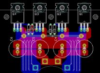
i'm currently playing around with a pcb for use with a computer powersupply to bring 240 volts down to 12v, then up to 35v.. and one area of the design is annoying me a little bit.. the trace length on the mosfets.
I have the layout symmetrical so the trace resistances(althoug minimal) will be identical on each side.
Also the trace length to the gates will be as short as possible.. however i cant get it that short.
In a computer motherboard the trace distance between the mb SMPS PWM controller and the gate of a mosfet is around 2cm at most..however its all surface mount which makes mounting easy.. even easier as they use 4 or even 6 layer PCBs
the current trace distance from the output of the SG3525 and the input on the mosfet, is.. as measured at around 8cm for the right mosfet, and around 6cm for the right mosfet. this is one side. it is identical to the other 2 mosfets.. as i said its symmetrical.
Included is a picture, your thoughts/opinions please.
An externally hosted image should be here but it was not working when we last tested it.
- Status
- This old topic is closed. If you want to reopen this topic, contact a moderator using the "Report Post" button.
- Home
- General Interest
- Car Audio
- SMPS - Why are my FETs cooking?