Hello,
I have a Sony TTs-4000 with a bad IC (I tested everything around it) :
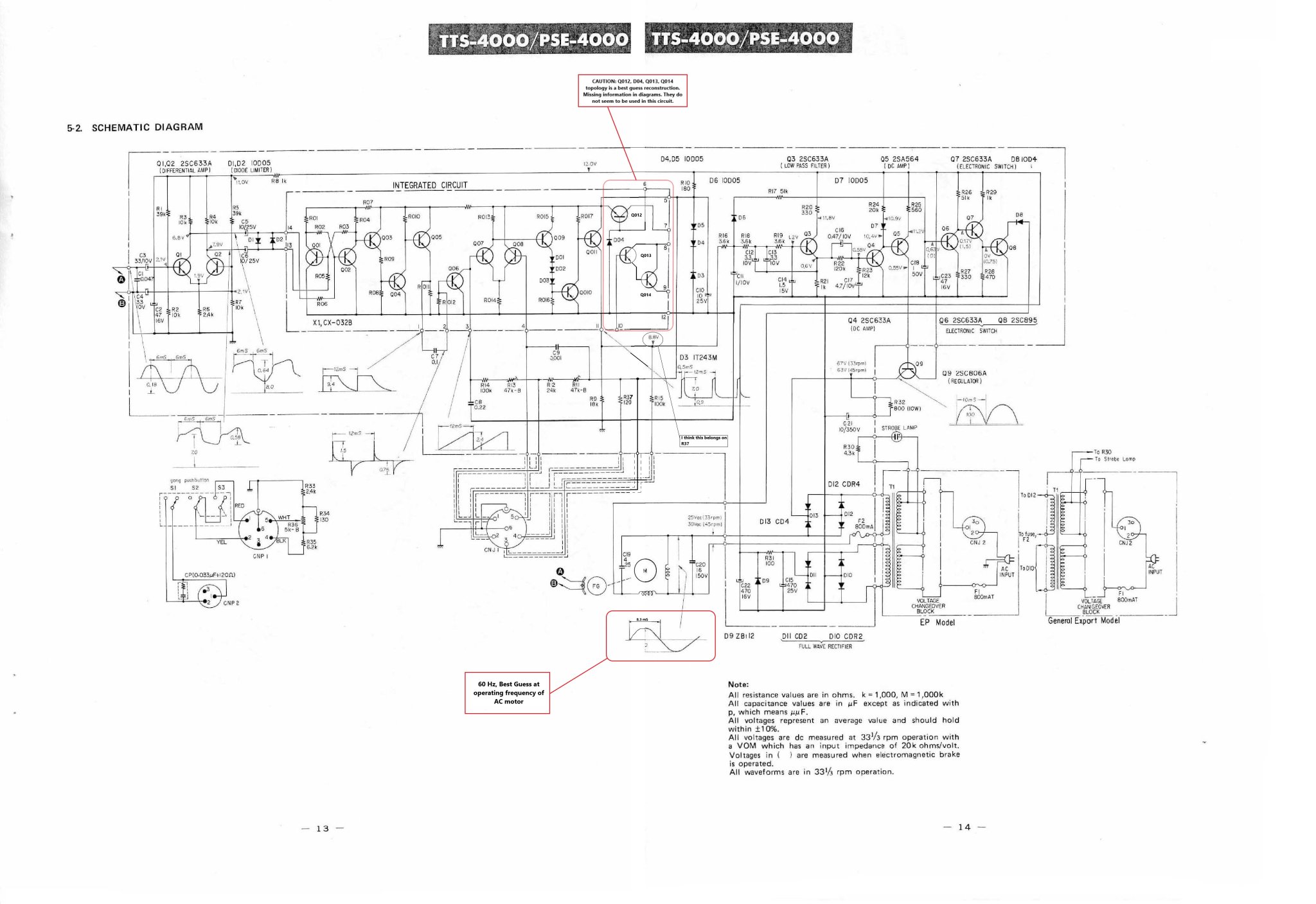
the custom made CX-032B also used in the TC-755 and TC-758 decks. This part seems impossible to find, B&D had one in stock but that's now gone as well. On the schematic for the tts-4000 there is a detailed drawing of the inside of this IC but the values are missing. My question is : is there anyone out there that has one of these and is willing to sell or, maybe the more importent question that could be useful to others as well, is there nyone who could build it with discrete components and or has information on the values that could help me build it ??
Thank you!
I have a Sony TTs-4000 with a bad IC (I tested everything around it) :
the custom made CX-032B also used in the TC-755 and TC-758 decks. This part seems impossible to find, B&D had one in stock but that's now gone as well. On the schematic for the tts-4000 there is a detailed drawing of the inside of this IC but the values are missing. My question is : is there anyone out there that has one of these and is willing to sell or, maybe the more importent question that could be useful to others as well, is there nyone who could build it with discrete components and or has information on the values that could help me build it ??
Thank you!
Attachments

Well, this doesn't seem to attract the interest I was hoping for. Does the fact that the service manual has a detailed description of what the circuit does help ? If not here, can anyone point me in the direction of someone that could help redesign this part ?
I'm going to ask if you have put a scope on this chip to confirm it is faulty? Passive component checks around the chip doesn't really go far enough. Spin the platter by hand if needed and check the oscillator is running and that the FG pulses are being handled correctly. Of course check the chip supply is correct as well, it looks Zener regulated.
Yes I did, sorry I mentioned this in a previous thread. The waveform is correct at pin 13 and 14 when the chip is removed but with it in place it badly distorts it and there is no output from pin 1 of the IC. The supply is working ok.
Was there anything on pin 3 which looks to be the oscillator? If that is dead as well then I would suspect the chip. If the waveform is present its worth a bit more thought and in that case it mnight be possible to come up with something to replace that left hand section of the chip containing the bistable multivibrator.
I got it out of the box again, plugged it in and it worked for about 20 secondes (never happened before) than it just started speeding up without end.
I scoped pin 3 and got nothing.
I scoped pin 3 and got nothing.
OK. If its running fast or if you turn the platter by hand you should see the FG pulses (clipped sine) on the collectors of both Q1 and Q2.
I was having a play...
With C5 and C6 removed you have an antiphase sine output on the collectors. Use DC coupling on a scope and note amplitudes.

With the caps in place:

This is the output at pin #1 If the chip was good you should at least get this far. I've guessed all the values but this part of the chip circuit is just a simple bistable multivibrator and level shifting output stage to give a clean 50:50 duty cycle squarewave derived from the FG input. I'm guessing the supply on pin #5 should be around 7.5 volts. The IT243M is drawn as a diode but must be a Zener in reality or according to the web, a B/E junction reverse biased which would breakdown at around 6 volts or so. Anyhow, I would guess around 7.5 volts in total on pin #5.
Thats as far as I have got 🙂

I was having a play...
With C5 and C6 removed you have an antiphase sine output on the collectors. Use DC coupling on a scope and note amplitudes.
With the caps in place:
This is the output at pin #1 If the chip was good you should at least get this far. I've guessed all the values but this part of the chip circuit is just a simple bistable multivibrator and level shifting output stage to give a clean 50:50 duty cycle squarewave derived from the FG input. I'm guessing the supply on pin #5 should be around 7.5 volts. The IT243M is drawn as a diode but must be a Zener in reality or according to the web, a B/E junction reverse biased which would breakdown at around 6 volts or so. Anyhow, I would guess around 7.5 volts in total on pin #5.
Thats as far as I have got 🙂

Thank you, this is most helpful !
Ok so with caps removed I have indeed two out of phase sinewaves (almost look square though) both are about 8v peak to peak and slightly pulsating. the collector of Q2 is at 8.4V and the collector of Q1 is at 5.5V. I'm doing this with f2 removed and turning the motor by hand because at the speed this thing is turning I'm afraid I might damage it. I'm getting about 8.5V on pin 5 and the sine looks similar to yours with the caps in place and well pin 1 and 2 look exactly like they do on the schematic and on your simulation so I guess you were right, the ic might be ok. I'm now also getting an output on pin 11 that looks like what's indicated in the schematic. so far so good I would say.
Ok so with caps removed I have indeed two out of phase sinewaves (almost look square though) both are about 8v peak to peak and slightly pulsating. the collector of Q2 is at 8.4V and the collector of Q1 is at 5.5V. I'm doing this with f2 removed and turning the motor by hand because at the speed this thing is turning I'm afraid I might damage it. I'm getting about 8.5V on pin 5 and the sine looks similar to yours with the caps in place and well pin 1 and 2 look exactly like they do on the schematic and on your simulation so I guess you were right, the ic might be ok. I'm now also getting an output on pin 11 that looks like what's indicated in the schematic. so far so good I would say.
Ok I don't understand what just happened, I put the fuse for the motor back in and it works 😵. Except removing the caps and putting them back in (which I already did several times before, I changed nothing.
the collector of Q2 is at 8.4V and the collector of Q1 is at 5.5V
Theoretically both should be the same but I notice with the simulation that differences in the two transistors can unbalance that very significantly. With identical devices I see 7.4 volts on each but change one transistor and it can be as extreme as 10v and 4v. Such an extreme imbalance alters the duty cycle a little but it still essentially all works the same.
I'm getting about 8.5V on pin 5
Useful to know. The two series diodes will add around 1.3 volts to whatever that 'Zener' is so lets say 8.5-1.3 = 7.2 volts. Sounds reasonable.
Ok I don't understand what just happened, I put the fuse for the motor back in and it works
These things happen and its frustrating. Could heat from the iron be a factor. I wonder if its worth changing those two input transistors just... because...
Do the legs look OK on them, not the dreaded 'black or green rot' working its way up 😀
The schematic itself also shows about 1V difference but I replaced both with a matched pair of 2SC1815 so I guess it should actually be closer (It didn't work even before that so I don't think that's the problem). I also replaced all the other transistors but that didn't matter either so I put the original ones back in place. All the caps have been replaced as well (all of this after initially testing it with the speeding problem as result.
I'm going to keep turning it on and off a few times a day, see if it stays ok.
I'm going to keep turning it on and off a few times a day, see if it stays ok.
 then.
then.These show the voltages with a perfect match and then with oddball transistors. It still all works though.
I'll check the resistors around the pair to see if something is off because those transistors were pretty closely matched. For now anyway it works, I'll keep you posted and if I finally (this has been sitting aside for almost a year) get it done I'll post a picture with the custom plinth and SME 12" arm 😀.
And even if the problem seems to have fixed itself, thank you very much for taking the time !
And even if the problem seems to have fixed itself, thank you very much for taking the time !

Hi!
It's still working but I wouldn't be against having one as a reserve. How much would you ask for one ?
It's still working but I wouldn't be against having one as a reserve. How much would you ask for one ?
Hi, for one unit and shipped to France it will be $20. You can pay me once you've received them.
Let me know if you're still interested
Let me know if you're still interested
Solder the joints and check switches. The filter caps may need replacement.
The fact it ran then quit points to the ic working
The fact it ran then quit points to the ic working
Perfect. I will send you a private message when I get back from my trip with my address.Hi, for one unit and shipped to France it will be $20. You can pay me once you've received them.
Let me know if you're still interested
Stocktrader200,
the board is fully recapped and now works perfectly as mentioned before, I'm being cautious and getting a spare just in case.
- Home
- Design & Build
- Parts
- Sony CX-032B