Be sure to use the correct LM385 with the correct part number suffix; if you accidentally use the incorrect LM385, the M2 amp will misbehave when supplying large output currents. For example, when playing loud into 4 ohm loads. See "Official M2 Schematic" thread post #13 for the correct LM385.
Yep, The M2OPS is making music ") .
.
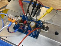
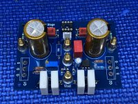
The pcb was easy to work with and solder. Initial power is fed from my lab bench supply (+/-24vdc). Input is configured for SE. Bias current was a bit high (1.7A) with 0R47 source resistors at R13, R14. Added 0R10 in series with 0R47 dropped current to 1.4A, probably should use 0R62 as Patrick suggested if heatsinks are borderline adequate. DC offset trimmed to 0mV and only drifted +/-5 over the next 60 minutes. No thumps/pops or noise of any kind is heard from the speaker when powered on/off. M2OPS is driving a small 2-way 4R speaker (Speedster's) and sounds very good. (subjective alert)
.The pcb was easy to work with and solder. Initial power is fed from my lab bench supply (+/-24vdc). Input is configured for SE. Bias current was a bit high (1.7A) with 0R47 source resistors at R13, R14. Added 0R10 in series with 0R47 dropped current to 1.4A, probably should use 0R62 as Patrick suggested if heatsinks are borderline adequate. DC offset trimmed to 0mV and only drifted +/-5 over the next 60 minutes. No thumps/pops or noise of any kind is heard from the speaker when powered on/off. M2OPS is driving a small 2-way 4R speaker (Speedster's) and sounds very good. (subjective alert
)Attachments

All of the existing opamp-based M2x input cards are unity gain buffers. None of them can be reconfigured for higher gain by changing component values or increasing bias currents.
However, if members want to lay out a new M2x compatible input PCB, the physical dimensions are shown in (post #56 of the M2x thread). You will quickly discover it has only four I/O signals, corresponding to the four attachment bolts: input, output, pos_23v, neg_23v . But Patrick's version in this thread needs one more "I/O bolt" , namely: signal ground. See resistor Rs in the schematic of post #24 in this thread. So you'll need to devise a way to add another connection between mother board and daughter board. The Melbourne project (link) shows one possible approach.
However, if members want to lay out a new M2x compatible input PCB, the physical dimensions are shown in (post #56 of the M2x thread). You will quickly discover it has only four I/O signals, corresponding to the four attachment bolts: input, output, pos_23v, neg_23v . But Patrick's version in this thread needs one more "I/O bolt" , namely: signal ground. See resistor Rs in the schematic of post #24 in this thread. So you'll need to devise a way to add another connection between mother board and daughter board. The Melbourne project (link) shows one possible approach.
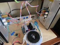
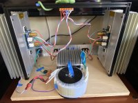
Stereo M2OPS Plank Amp is alive!Nelson has kindly approved publishing the Gerber files.
But I shall wait till Vunce has finished first, including power supplies.
Patrick
Trafo is an Antek AS-4220 and psu is Jkuetemann's "Simplified" capMx that was already built and sitting on a shelf. simplified-mrevil-pmi-capacitance-multiplier.241263
Trimpots adjusted to drop 2V5 across capMx for +/-24V M2OPS input.
Channel#1 still running 0R57 at R13 & R14 for 1.4A bias current, heatsink 47C.
Channel#2 has 0R62 at R13 & R14 for 1.25A bias current, heatsink 45C.
ZM's Iron Pre is driving the M2OPS and I'm enjoying this combo
I have a pair of MeanWell SMPS units on the way to try out......
Attachments
- Home
- Amplifiers
- Pass Labs
- The M2 Output Stage in Class A/B, and maybe a Power WHAMMY?