Hello everyone!
Currently, only the LTSPICE simulation has been completed. Moving forward, I plan to share completed schematics, gerbers, and a BOM. Additionally, I'm working on a bidirectional LED driver based on an H-bridge.
I want give shoutout to @Extreme_Boky for suggesting the idea of a transistor-based flip-flop!
This board will enable DIYers to integrate ON/OFF functionality into any project. The separation of high-voltage switching from the low voltage logic is achieved through a 16A non-latching relay with 360Ω coil. Board allows for a nice low voltage switch, anti-vandal type, and most of those feature a built-in LED ring. A compact 1W MeanWell SMPS is utilized to power the board at all times to monitor user input.
Biggest reason for choosing a transistor-based design for this board was to minimize power consumption. During idle operation, the board will consume only 2mA, primarily for monitoring user input. When the user presses the button, the flip-flop switches to its alternate branch, activating constant current sources for the relay and LED. The LED's brightness can be adjusted by varying the current from 0.3mA to 20mA. The relay driver circuit incorporates a 15ms delay to latch the relay at full 33mA current, which then reduces to 14mA. As a result, during normal ON operation, the board should consume only approximately 20mA.
Feedback and suggestions are highly appreciated!
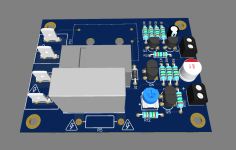
Draft of the board in 3D is ready and attached!
Currently, only the LTSPICE simulation has been completed. Moving forward, I plan to share completed schematics, gerbers, and a BOM. Additionally, I'm working on a bidirectional LED driver based on an H-bridge.
I want give shoutout to @Extreme_Boky for suggesting the idea of a transistor-based flip-flop!
This board will enable DIYers to integrate ON/OFF functionality into any project. The separation of high-voltage switching from the low voltage logic is achieved through a 16A non-latching relay with 360Ω coil. Board allows for a nice low voltage switch, anti-vandal type, and most of those feature a built-in LED ring. A compact 1W MeanWell SMPS is utilized to power the board at all times to monitor user input.
Biggest reason for choosing a transistor-based design for this board was to minimize power consumption. During idle operation, the board will consume only 2mA, primarily for monitoring user input. When the user presses the button, the flip-flop switches to its alternate branch, activating constant current sources for the relay and LED. The LED's brightness can be adjusted by varying the current from 0.3mA to 20mA. The relay driver circuit incorporates a 15ms delay to latch the relay at full 33mA current, which then reduces to 14mA. As a result, during normal ON operation, the board should consume only approximately 20mA.
Feedback and suggestions are highly appreciated!
Draft of the board in 3D is ready and attached!
Attachments


Last edited:


