Hi everyone, recently I've been updating a little spreadsheet for designing power and output transformers and filter chokes for tube amplifiers.
The early version of this was designed by myself around 2015 and it was mostly based on Patrick Turner design method, but it was far too complicated that Patrick himself didn't like it at all!
so I decided to update it so everyone interested in winding his own transformers can use it.
So here it is; a little spreadsheet for designing power transformer, single ended and push pull output transformers, and also power supply filter chokes.
The spreadsheet is pretty much self explainatory and someone needs only to follow the steps and fill the green cells using cell comments, but if there is any questions I'll be glad to help.
Regards
Sajad
Attachments
Thank you, Sajad! That's a valuable contribution and a great tool for DIY constructors to get an idea of what is involved and what a well-specified transformer looks like. Also helps iron shoppers distinguish between the good, the bad and the ugly !
Patrick and I talked a number of times about practical transformer design. His aim was to develop a systematic, practical design tool to help him in his own builds AND to help him set specifications for someone who might build a batch of transformers to his specification.
But every time we started to flow-chart the design process, Patrick would have second thoughts. The key problem (as he saw it) was the need to iterate - to build and test and then re-configure as required in order to arrive at a prototype that would deliver the intended performance. All very well when you want to build a good number of transformers, but not so good for DIY, where the builder is essentially building a prototype each and every time, with all the problems that poses.
Which I suppose a way of saying that good transformer buiders are treasures! Anyone who owns one of the (very few) amps for which Patrick wound his own will know just what I mean.
IMHO the key for designing a good transformer is trial and error.
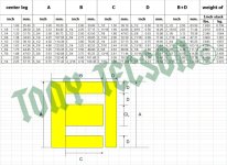
with this method there are three steps, the first step is filling the green cells at the top.
After that the calculator will give you minimum possible core stack area, based on that the second step is to enter your lamination dimensions so the stack area is larger than the calculated value.
The final step is to enter wire size within the minimum and maximum calculated values.
After that you should play around with the wire size and minimum frequency response to fill the whole winding window length and not to exceed max 85 percent of window height, so it is all trial and error.
I found the transformers which I built using this method pretty much passed all of the tests and turned out very close to the design goals.

Thank you for this, your contribution is much appreciated.
Regarding the PSU Choke, I gather the Excel calcuation is for CLC not LC which would require a different design; swinging choke with different iron/copper ratio. I am unsure what changes would be needed to the formula for an LC choke but understand the ripple voltage would come into play. Would it be possible for you to include another tab for LC choke designs.
regards
to design a ptx for a tube power amp, these are steps i take,
1. choose the topology and the tubes therein, tabulate the filament voltages and currents to know the total filament power..
2. know the output power in watts, if say 50 watts, the input power is 50/0.64 or 78 watts, this is for stereo channels. Assume class B.
3. add 1 & 2 to get the total power, say #1 is 40 watts, so total then is 78 + 40 or 118 watts..
4. determine the ptx primary volt amperes, 118/0.6 or 197 volt amperes, say 200 VA.....
this is how i do my ptx... others may disagree, but this is how i do it...
Well done, Sajad. Tough subject. Keep at it ! Some points on Audio p-p types:
I notice you use the default Bmax at 14,000 gauss which for me is too high; with M6 sheet I wind for10,000 gauss or 1T max. and design around the early industry line of the 1.4% iron distortion 2nd harmonic criteria, at f-3dB cutoff freq, as the start. This implies working around the Steinmetz law.
I can see that my transformers are bigger. Also comes up the situation of the number of interconnecting secondaries of maintaining the balance throughout the transformer; anyone who designs using 4 balanced sectioned secondaries will immediately notice there is an integer problem with the 8 ohm configuration; that is to create this connection, two sec windings must be paralleled and two in series. ideally then we have configurations for 2:4:8:16 ohms. Users who have this configuration should do a dummy amp check set up with the flying wire secondaries to check for the best winding configuration to give the best squarewave quality.
So the next issue arrives; my transformers typically don´t stretch above 50Khz, as more primary wire and larger cores can without sectioned interlayers reduce the high frequency capabilities. Alas, the stumbling block, the leakage capacitance and inductance.
Bench Baron
Thank you Benchbaron for your feedback. Yes you're right, 1.4T is a little too much for GOSS but You can change the max flux to whatever you want. The reason I used this value was to compare my results with Patrick Turner's website example. He used 3% of THD as a goal in the -3dB LF pole frequency, so at this point Vac becomes around 0.71 of max voltage and it prevents the core from further increase in THD, but aiming for 1.4% THD would be a better practice.
i design for below 1T even for M6, and around 0,6T for M50 cores..I notice you use the default Bmax at 14,000 gauss which for me is too high; with M6 sheet I wind for10,000 gauss or 1T max. and design around the early industry line of the 1.4% iron distortion 2nd harmonic criteria, at f-3dB cutoff freq, as the start. This implies working around the Steinmetz law.
Yeah he completely bombarded me with 'idiot generation' and 'computer nerds'. 😂😂Thanks Sajad. I've recently started researching this subject, Having exchanged a few email's with Patrick I can imagine his emails to you on the subject must have been interesting : ) He was very forthright.
Andy.
Turner used 3% LF pole frequency...that makes for a smaller core, however I can see with a fair amount of gnfb that figure drops.
By chance, I am in the finishing stages of a dual traditional 3 stage 120W power amp each using parallel pp 6550C 2K A-A, 40%UL with 4 identical secondaries, so configuration can be changed to 1-4-8ísh-16 Ohm loads to my own Williamson design, which was wound by a winding house.
Enclosed is the typical distortion bathtub curve diagram at 25dB upper graph (lower graph gnfb at 19dB); note of the low end thd that extends well into single frequency range before sat troubles start. The transformer spec was designed around the 1.4% criteria with Bmax 1T; primary resistance each half 20 ohms with UL tap 13 ohms. Fixed bias operation with 450V B+. Each Tube quies 70mA # 125mA full output. 25dB. I ignored the 1W level specifications as here I am dealing with power response.
It was expected the HF end is a little compromised considering the higher frequency advantages of parallel push pull, but neverless the midrange and squarewave performance is exemplary. The initial calculated transformer spec at f-3dB cutoff was 15Hz and 40Khz. In reality the distortion curve at the top end response indictates fairly high leakage parasitics, typical of such large designs.
Many of us have different approaches on this tricky topic, though when I worked on tube amps in the 1960´s, the Williamson & Partridge 1.4% f3 LF cutoff standard may seem very generous by today´s standards. However these were the best designs of the day.
On hindsight, the low frequency power performance is excellent, but a smaller transformer would have improved the top end. There is a case for even higher amounts of gnfb which would reduce the distortion and signal to noise further, though 25dB was used in my design, equating to hum and noise of -75dB down below full output. The circuit can accept another 25dB gnfb increase before top end stability issues become noticeable.
On a cautious note; the output stage tubes cannot be expected to handle frequencies below transformer cutoff as with a low primary resistance and unforgiving overload situation can arise. In this amplifer, a Chebychev high slope HP filter was added to the front end.
Bench Baron
Thank you so much Bench Baron, very helpful info, I have no experience with EI GOSS and only used NOSS EI for my transformers and often used 0.8T to 1T as my design goal. The only GOSS I ever used was double C cores which worked perfect with 1.4T. I will edit the spreadsheet with 1T flux as the recommended value for OPT design.
So how about NOSS, what's your recommended max flux density with this material for OPTs?
So how about NOSS, what's your recommended max flux density with this material for OPTs?
You will not get a disagreement from me 😄to design a ptx for a tube power amp, these are steps i take,
1. choose the topology and the tubes therein, tabulate the filament voltages and currents to know the total filament power..
2. know the output power in watts, if say 50 watts, the input power is 50/0.64 or 78 watts, this is for stereo channels. Assume class B.
3. add 1 & 2 to get the total power, say #1 is 40 watts, so total then is 78 + 40 or 118 watts..
4. determine the ptx primary volt amperes, 118/0.6 or 197 volt amperes, say 200 VA.....
this is how i do my ptx... others may disagree, but this is how i do it...
Conservative design rules
See post #2 by Sch3mat1c ...(2003...old closed thread)......how about NOSS, what's your recommended max flux density with this material for OPTs?
quote...."The only difference is that C-cores tend to have a higher mu, hence fewer turns can be used, and more bandwidth. Fewer turns also means a smaller core is necessary for the same power level.
But then, you can get GOSS (Grain-Oriented Silicon Steel, as opposed to generic transformer iron, NOSS (Non-Oriented ..)) in E-I shapes as well, so there is absolutely no difference.
I would use same flux density.
BB
Turns number to core are optimized primarily from flux density perspective, not mu, when power transfer is prioritized, in the application of output and power transformers. This is misleading. The primary goal is to calculate the number of turns to core area necessary for the maximum voltage amplitude at lowest frequency necessary at the needed maximum flux density. For SE transformers, one adds DC flux density as well.
Mu as priority comes in little audio transformer applications, such as input transformers, where flux density is of smaller problem compared to inductance for small turn count.
Most modern magnetic materials do not require worrying for permeability insufficiency for power transformers, SE and even PP transformers. For most cases, flux density leads the criteria.
In the case of C cores, I've only found permeability insufficiency in badly cut C cores with huge "inherent" airgaps.
Last edited:
- Home
- Amplifiers
- Tubes / Valves
- Tube amp transformer calculator spreadsheet