Hello Forum Members,
I am currently building a Honey Badger. I have one board finished and will start the other one tomorrow. I would like to begin putting together a parts list for the PSU.
I will be using a toroidal transformer with dual secondaries that produces 45 volts and is rated at 625VA according to the manufacturer. I recently received my V3 universal power supply pcb and suddenly have more questions than answers. The potential options are overwhelming. I am relatively new at this and could use some guidance.
I've done some research on this thread and found a lot of information, most of which doesn't help me decide how to choose components and populate my board. There are some basic PSU recommendations in the Honey Badger build guide but it doesn't get specific.
I would like to keep the V3 board intact and use on-board rectifiers because this would reduce the wiring involved in using bridge rectifiers.
My questions:
Do I need to utilize the optional Pi resistors?
Can I forego snubbers since this is a Class AB amp?
Do I connect the ground tabs of the board even though I'm using dual secondaries?
How do I calculate the resistor value of the LED resistors with 63 volt rails?
I apologize for the basic nature of these questions, but power supplies confuse me and I'm pretty new at this. If anyone has built the Honey Badger and sorted through these decisions I could use some guidance. Even a BOM or photo of a finished HB PSU would be helpful. Thank you in advance for your time and patience.
No.
Always forgo the output snubber. Input snubber a good idea if you have Quasimodo. If not, just leave empty.
Yes, you need a bipolar (+/-) supply. Make sure you understand how to connect this.
Roughly 1K per volt, so use something around 60k resistor.
Always forgo the output snubber. Input snubber a good idea if you have Quasimodo. If not, just leave empty.
Yes, you need a bipolar (+/-) supply. Make sure you understand how to connect this.
Roughly 1K per volt, so use something around 60k resistor.

I am currently building a Honey Badger. I have one board finished and will start the other one tomorrow. I would like to begin putting together a parts list for the PSU.
I will be using a toroidal transformer with dual secondaries that produces 45 volts and is rated at 625VA according to the manufacturer. I recently received my V3 universal power supply pcb and suddenly have more questions than answers. The potential options are overwhelming. I am relatively new at this and could use some guidance.
I've done some research on this thread and found a lot of information, most of which doesn't help me decide how to choose components and populate my board. There are some basic PSU recommendations in the Honey Badger build guide but it doesn't get specific.
I would like to keep the V3 board intact and use on-board rectifiers because this would reduce the wiring involved in using bridge rectifiers.
My questions:
Do I need to utilize the optional Pi resistors?
Can I forego snubbers since this is a Class AB amp?
Do I connect the ground tabs of the board even though I'm using dual secondaries?
How do I calculate the resistor value of the LED resistors with 63 volt rails?
The is no end of learning about all this stuff
If the dual secondaries on the 625 VA transformer are 45 Vac , that will give about +/- 62 Vdc rails .
From what I understand , anything above 50 Vdc can be lethal . Which , as I'm told , why fork lifts run on 48Vdc .
PLus with large electrolytic caps charged up to 62 Vdc , you'll be able arc weld with this .
I don't know the Honey Badger Amp , but does it really need +/- 62 Vdc rails ?
People often avoid suggesting actual component makes and models on the site ,
because even the slightest hit of " boutique " audio components , breaks out into argument about
spending silly money on " boutique " components .
However, highly recommend buying components of off well known electronics vendors ... and not Eb y .
Actually , depending on the vendor , shipping is free with an order above $100 or $200 .
Know that the layout of the grounding on a power amp is critical .
There are typically 2 types of grounds - Hydro Earth - any metal case must be connected to HE .
The Rod Elliot Article is a classic on this subject . Note figure 3 and 5
https://sound-au.com/earthing.htm
The other ground is audio ground - The audio ground is "lifted " from Hydro Earth ground as shown in Rod Elliots article .
For analog ground , a technique called star grounding should be used .
The idea is that all parts of the amp are referenced to the same " 0 " Vdc .
So the RCA ground , power supply ground , amp board ground , and speaker ground are all referenced to the same "0" Vdc .
This node is usually placed somewhere in the middle between the RCA's , speaker terminals , power supply and amp board .
Suggest using 12 awg minimum wire except for the RCA ground .
Suggest using the Pi resistors - those 3 W Panasonic metal oxide power resistors are very popular on this site .
Resistor noise is an entire topic . After trying Mundorf metal oxide resistors - I'll be going back to metal film and wire wound resistors .
I've bought these
https://www.mouser.com/ProductDetail/TE-Connectivity-Holsworthy/RR03JR33TB?qs=HLeXuo0aL2ptw2OFbvbUcQ==
But they are affected by a magnet - fights break out over the issue of magnetic vs non magnetic resistors.
Mount the power resistors on your board so there is an air gap under neath them .
Note : its critical that the first bank of electrolytic caps on the power supply board be able to handle the ripple current .
.
I am currently building a Honey Badger. ... will be using a toroidal transformer with dual secondaries that produces 45 volts ...
Looking into this , the Honey Badger amp schematic shows supply rails of +/- 60 Vdc .
People get into arguments and make mocking comments about resistor types , but say nothing about +/- 60 Vdc supply rails .
I'll refrain from making a comment .
However , know that anything above +/- 48 Vdc , can be lethal .
Wear rubber dish washing gloves when taking measurements .
I've made some suggestions on power diode types on the previous page .
https://www.diyaudio.com/community/threads/v3-universal-power-supply-circuit-board.238918/page-27
Also , note the diode pin out requirement for the V3 board .
Please know I am absolutely no authority on PN junctions ( aka diodes ) .
But I thought these were a compromise " good value . "
https://www.vishay.com/docs/94796/vs-60aph03-n3.pdf
Highly , recommend you build the power supply board one stage at a time .
The power diodes need a load to be able to take a measurement .
So suggest soldering on 4 power diodes with heats sinks at together , then temporarily solder on a resistor with no supply caps .
Maybe 10 K , 1 W resistor load and take a measurement.
If that works out fine , then solder on the other power diodes with sinks .
Also , I highly recommend you add a Fo Felix DIY EMI filter to your build .
Connect it after the power switch .
I was told on this site that both the hot and neutral should be switched - not just the hot .
.
.
Thanks for your response Uunderhill. I actually had the toroid on hand which is one of the reasons I chose the Honey Badger. Other than this I wouldn't need that amount of voltage.
I am up-to-speed on how to safely wire the IEC to the chassis for safety earth ground.
Wiring the secondaires to the PSU will take some study. I definitely don't want to blow up any capacitors. I respect electricity and am very cautious by nature so I will be posting pics and asking for feedback prior to powering up the amp initially. I also have a variac and dim bulb tester when the time comes. Most of my confusion centered on the pcb itself and how to tailor it to my needs. I will look into protective gloves.
Thanks for the link to the Rod Elliot article. I appreciate the resource and will definitely study it thoroughly. Cheers!
Dave M.
Most of my confusion centered on the pcb itself and how to tailor it to my needs.
6L6 has a complete discussion on wiring the board .
Suggest soldering the jumper wires first .
A schematic comes with the board - the power diodes are just wired in a bridge configuration .
Its very similar to the F5 power supply shown here in post #1
https://www.diyaudio.com/community/threads/f5-psu.211649/
The issue maybe that the V3 schematic shows 2 diodes in a single TO-247 case .
Looking at the board , you'll see pins 1 and 3 of the power diodes are connected
So the 2 diodes in TO-247 case are wired in parallel .
Make sure you buy diodes that match the pin out of this board .
As for the LED resistor , as I recall the voltage drop across a forward biased LED is 2.2 Vdc
and the max current is 10 mA - but go with something like 6 mA .
10 K = ( Vrail - Vfb ) / bias current = ( 62 Vdc - 2.2 Vdc ) / 6 mA
Its going to be dissipating 0.36 Watts . Typical me , I way over rate components , so go with 1 Watt
.
Thanks for your response Uunderhill. I actually had the toroid on hand which is one of the reasons I chose the Honey Badger. Other than this I wouldn't need that amount of voltage.
I am up-to-speed on how to safely wire the IEC to the chassis for safety earth ground.
Wiring the secondaries to the PSU will take some study. I definitely don't want to blow up any capacitors.
Actually , do you have a small 50 VA or 100 VA transformer with something like 9 or 12 Vac secondaries ?
If so , you could temporarily lightly solder on one secondary to the Power Supply board and test the board this way .
Again try to build up the board 1 stage at a time , then when the board is totally populated , then solder on the 625 VA beast .
Also , remember the supply is always going to need a load to take measurements .
A temp load resistor of something like 10 K at 1 W will be fine .
As for the Honey Badger , the power supply rails are fused .
I was prototyping an Amp and at low currents it performed beautifully .
But when the bias current was stepped up to 1 3 Amps , there was hum on the output .
I traced this down to temp power supply , where I installed different fuse ratings on the output .
Turns out that at 1.3 Amps , the voltage drop was different for the different fuse ratings .
6L6 has graciously provided a step by step series of photos .
https://www.diyaudio.com/community/...cuit-board-v3-illustrated-build-guide.244788/
.
How can I be sure that the capacitor I am choosing has sufficient ripple current capacity? I see ratings on Cap data sheets for ripple current ratings at low and high frequencies. However, I am unsure how much ripple current my amp would draw.Note : its critical that the first bank of electrolytic caps on the power supply board be able to handle the ripple current .
.
Do you go by the average current rating of the amplifier circuit? Is there a margin of safety one should build-in when choosing?
Thank you in advance to everyone who has been patient and helpful to this "newbie." I am learning a great deal.🙂
Its important to know that with a CRC or CLC passive power supply ,
the ripple on the first set of caps is significantly higher than the ripple on the output set of caps .
The ripple affects the lifetime of the cap .
The issue is to calculate the ripple , the capacitance value needs to be known , as well as the load current .
The power dissipated inside the cap = I^2 x ESR.
So for the first set of caps , its preferable to select caps a low ESR rating , and preferably a temp rating of 105oC .
Also , with +/- 62Vdc rails , you'll need a cap with a minimum 80Vdc voltage rating .
I'm hearing the price escalate with every spec requirement .
The good news is that the Honey Badger amp runs in Class A/B .
I don't see a spec for the quiescent current , but as a class A/B amp , it can't be too excessive .
It won't be in the order of a class A Amp .
Suggest reading through the Honey Badger discussion to learn from other people's experiences building this amp .
Yes its 255 pages long , but no doubt there will be some good info in it .
https://www.diyaudio.com/community/threads/diyab-amp-the-honey-badger-build-thread.211905/
.
Thanks @Uunderhill. You have been a ton of help to me. I will study the HB thread to learn more about this.
You were correct in one of your previous posts. There truly is no end to learning about this stuff. That's OK though, it helps me build a better amplifier. 🙂
You were correct in one of your previous posts. There truly is no end to learning about this stuff. That's OK though, it helps me build a better amplifier. 🙂
I do appreciate these resistors are to long to lay flat on the board .
In the 1960's , hand held 9 transistor AM radios , with 9 v batteries , had resistors mounted vertically on the board
so everything could be packed in the case . So rather than bending the leads multiple times , trying to mount these resistors parallel to the board ,
suggest mounting them using an upside down V shape .
.
On this website , any attempt to discuss various resistors sends out an invitation to many jesters .
Even with serious attempts to discuss resistor noise , jesters can't help themselves .
https://www.diyaudio.com/community/threads/what-causes-resistor-distortion.347259/
There is the text book equation for thermal noise - but notice equation shows thermal noise is independent of the resistive material .
But as it turns out , in the audio bandwidth , current noise dominates .
https://www.eetimes.com/selecting-r...lifier-and-other-high-end-audio-applications/
In the audio bandwidth , I tend to think of a resistor as a resistive element in series with noise generators .
The issue of magnetic vs non magnetic resistors gets into heated debates . So I ain't going there .
As I mentioned above , those 3 W Panasonic metal oxide power resistors are quite popular on this this site .
But after trying metal oxide power resistors in series with a metal dome tweeter , I soon switched back to wire wound resistors .
Going out on a limb , my own belief is to avoid industrial power resistors . However , non magnetic power resistors designed for audio
have become silly expensive . So I've been using those 3W metal film ones listed above - which are very reasonably priced .
To answer your question , the ER58 series use copper alloy leads , so I'd say use them .
.
Hello Forum Members,
I am currently assembling a V3 Universal PSU board for my Honey Badger build. The transformer used will be a 625 VA version with dual secondaries. The output voltage is 45-0-45.
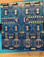
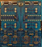
I would like feedback on the attached photos since I am new at this and a little unsure of myself. When working with high voltage, I would rather be "safe than sorry," as the saying goes. It is my understanding that for the purposes of my Honey Badger, snubbers and Pi resistors are not required.
My specific questions are: Does the board look like it is assembled properly as it relates to the jumpers? Are there any obvious errors in assembly at this point? I want the bleeder resistors (R9, R10) for safety reasons and they are 22k, 3 watt, flame resistant versions. The LED's are green with 60k resistors (R20, R21), as the rails will be about 62 volts.
I have not yet installed the heatsinks, capacitors or diodes as they would have obstructed the view of the current components.
Thank you in advance for your help!
Dave M.
I am currently assembling a V3 Universal PSU board for my Honey Badger build. The transformer used will be a 625 VA version with dual secondaries. The output voltage is 45-0-45.
I would like feedback on the attached photos since I am new at this and a little unsure of myself. When working with high voltage, I would rather be "safe than sorry," as the saying goes. It is my understanding that for the purposes of my Honey Badger, snubbers and Pi resistors are not required.
My specific questions are: Does the board look like it is assembled properly as it relates to the jumpers? Are there any obvious errors in assembly at this point? I want the bleeder resistors (R9, R10) for safety reasons and they are 22k, 3 watt, flame resistant versions. The LED's are green with 60k resistors (R20, R21), as the rails will be about 62 volts.
I have not yet installed the heatsinks, capacitors or diodes as they would have obstructed the view of the current components.
Thank you in advance for your help!
Dave M.
Attachments
A dual secondary transformer has 2 distinct pairs of secondaries , such as 45 - 0 Vac and 45 - 0 Vac .
A transformer with 45 - 0 - 45 Vac secondaries is generally referred to as a center tap transformer .
The diode bridge is wired totally different for a center tap transformer .
.
A transformer with 45 - 0 - 45 Vac secondaries is generally referred to as a center tap transformer .
The diode bridge is wired totally different for a center tap transformer .
.
Last edited:
Thanks for the reply @Uunderhill!
It appears that I know even less than I feared. Looking at the mechanical drawing I am pretty sure that my transformer has two secondaries and my description as 45-0-45 was an example of my limited knowledge.
I will post the data sheet with the mechanical drawing showing the windings as soon as I can separate that page from the other 5 pages listing all the possible ratings of this transformer. Thank you for your assistance and your patience with newcomers such as myself.
- Home
- The diyAudio Store
- V3 Universal Power Supply Circuit Board