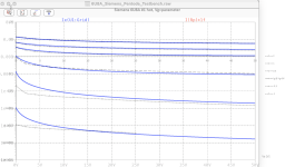
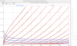
*Siemens 6U8A #pentode LTspice model based on the generic tetrode / g3-grounded pentode model from Adrian Immler, version i6
*A version log is at the end of this file
*Params fitted to datasheet graphs by Adrian Immler, May 2024
*This model is accurate for Vg up to 1.5V (up to 3V when "triode connected")
*The fit quality is presented at adrianimmler.simplesite.com
*This model is an enhancement of Adrians generic triode model to achieve tetrode/pentode behaviour.
*Hence, it is also suitable when the tetrode/pentode is "triode connected".
*Convenient for tetrodes, power beam tetrodes and g3-grounded pentodes.
*Copes secondary emission effect!
*            Pentode section of the tube
*            | SI=Siemens construction. Be aware of a very different 6U8A constr. with large plate window!
*            | | i6 version is identical to the i5, but measurements done with HOT anode for highest accuracy
*            | | |  plate. Note: For backward-compatibility, the anode A means P connected to G2
*            | | |  | grid2 (screen)
*            | | |  | |  grid
*            | | |  | |  | cathode
*            | | |  | |  | |
.subckt 6U8A#P.SIi6 P G2 G K
+ params:
*Parameters for space charge current Is (100% assigned to Ia @ Vg < 0)
+ mu   = 43    ;Determines the voltage gain @ constant Ia
+ rad  = 3k77   ;Differential anode resistance, set @ Iad and Vg=0V
+ Vct  = 0.58  ;Offsets the Ia-traces on the Va axis. Electrode material's contact potential
+ kp   = 178   ;Mimics the island effect
+ xs   = 1.5   ;Determines the curve of the Ia traces. Typically between 1.2 and 1.8
+ kIsr = 16m   ;Va-indepedent part of the Is reduction when gridcurrent occurs
+ kvdg  = 65   ;Va-depedent part of the Is reduction when gridcurrent occurs
*
*Parameters for assigning the space charge current to Ia and Ig @ Vg > 0
+ kB   = 0.15  ;Describes how fast Ia drops to zero when Va approaches zero.
+ radl = 100   ;Differential resistance for the Ia emission limit @ very small Va and Vg > 0
+ tsh  = 8     ;Ia transmission sharpness from 1th to 2nd Ia area. Keep between 3 and 20. Start with 20.
+ xl   = 1.3   ;Exponent for the emission limit
*
*Parameters of the grid-cathode vacuum diode
+ kg = 440     ;Inverse scaling factor for the Va independent part of Ig (caution - interacts with xg!)
+ Vctg = -0.1  ;Offsets the log Ig-traces on the Vg axis. Electrode material's contact potential
+ xg   = 1.0   ;Determines the curve of the Ig slope versus (positive) Vg and Va >> 0
+ VT   = 0.088 ;Log(Ig) slope @ Vg<0. VT=k/q*Tk (cathodes absolute temp, typically 1150K)
+ rTr  = 0.95  ;ratio of VT for Igr. Typically 0.8
+ kVT  = 0     ;Va dependant koeff. of VT
+ gft1 = 0     ;reduces the steering voltage around Vg=-Vg0, for finetuning purposes
+ gft1a= 0     ;reduces the steering voltage around Vg=-Vg0. Effect decreases with 1/(1+kB*Va)
+ gft2 = 2     ;finetunes the Igr drop @ incrasing Va and around Vg=-Vg0
*
*Parameters for the caps
+ cpg  = 0p01  ;From datasheet
+ Cg2g = 4p2   ;measured at the golden sample, filament not heated
+ cpk  = 2p6   ;From datasheet
+ cgk  = 5p0   ;From datasheet
*
*parameters needed to enhance the triode model to a tetrode model
+ mu2 = 80     ;1/mu2 is the fraction of Vp which together with Vg2i builds the virtual Triode-Anode Voltage
+ kB2 = 0.3    ;Describes how fast Ip drops to zero when Vp approaches zero.
+ fr2 = 0.20   ;determines the residual ig2 fraction @ high Va values
+ radl2 = 2k9  ;Differential resistance for the Ip emission limit @ very small Vp and Vg > 0
+ tsh2  = 6    ;Ip transmission sharpness from 1th to 2nd Ip area. Keep between 3 and 20. Start with 20.
+ xl2   = 0.8  ;Exponent for the Ip emission limit
*
*special purpose parameters
+ os = 1       ;Overall scaling factor, if a user wishes to simulate manufacturing tolerances
+ murc = 10    ;Mu of the remote cutoff triode
+ ksrc = 10G   ;Inverse Iarc gain factor for the remote cuttoff triode
+ kprc = 1k    ;Mimics the island effect for the remote cotoff triode
+ Vbatt = 0    ;heater battery voltage for direct heated battery triodes
+ Vdrmax = 100 ;max voltage of internal Vg drop, for convergence improvements
*
*Calculated parameters
+ Iad = {100/rad} ;Ia where the anode a.c. resistance is set according to rad.
+ ks = {pow(mu/(rad*xs*Iad**(1-1/xs)),-xs)} ;Reduces the unwished xs influence to the Ia slope
+ ksnom = {pow(mu/(rad*1.5*Iad**(1-1/1.5)),-1.5)} ;Sub-equation for calculating Vg0
+ Vg0 = {Vct + (Iad*ks)**(1/xs) - (Iad*ksnom)**(2/3)} ;Reduces the xs influence to Vct.
+ kl = {pow(1/(radl*xl*Ild**(1-1/xl)),-xl)} ;Reduces the xl influence to the Ia slope @ small Va
+ kl2 = {pow(1/(radl2*xl2*Ild2**(1-1/xl2)),-xl2)}
+ Ild = {sqrt(radl)*1m} ;Current where the Il a.c. resistance is set according to radl.
+ Ild2 = {sqrt(radl2)*1m}
*
*enhancement to derive a tetrode / g3-grounded pentode from a triode model
Bpa P A V=v(P,Ki) - (v(P,Ki)/mu2 + v(G2,Ki));voltage source to set Va, and to "measure" Ia
Bg2 G2 A I=i(Ra)*((1-fr2)/(1+kB2*max(0,v(P,Ki)))+fr2)
Bg2l G2 P I=uramp(i(Bpa)-smin(1/kl2*pow(v(Phc),xl2),i(Bpa),tsh2)) ;Ia emission limit
Bphc Phc 0 V=uramp(v(P,Ki)) ;Anode voltage, hard cut to zero @ neg. value
*
*Space charge current model
Rak A K 100G ;avoids "floating net" errors
Bft   ft 0 V=1/(1+pow(2*abs(v(G,Ki)+Vg0),3)) ;an auxiliary voltage to finetune the triode around Vg=-Vg0
Bggi GGi 0 V=(v(Gi,Ki)+Vg0)*(1/(1+kIsr*max(0, v(G,Ki)+Vg0))) - gft1*v(ft) - gft1a*v(ft)/(1+kB*v(Ahc)) ;Effective internal grid voltage.
Bahc Ahc 0 V=uramp(v(A,Ki)) ;Anode voltage, hard cut to zero @ neg. value
Bst   St 0 V=uramp(max(v(GGi)+v(A,Ki)/(mu), v(A,Ki)/kp*ln(1+exp(kp*(1/mu+v(GGi)/(1+v(Ahc)))))));Steering volt.
Bs    Ai Ki I=os/ks*pow(v(St),xs) ;Langmuir-Childs law for the space charge current Is
*Bstrc Strc 0 V=uramp(max(v(GGi)+v(Ahc)/(murc), v(Ahc)/kprc*ln(1+exp(kprc*(1/murc+v(GGi)/(1+v(Ahc)))))));FOR REMOTE CUTOFF TUBES ONLY
*Bsrc   Ai Ki I=os/ksrc*pow(v(Strc),xs) ;FOR REMOTE CUTOFF TUBES ONLY
*
*Anode current limit @ small Va
.func smin(z,y,k) {pow(pow(z+1f, -k)+pow(y+1f, -k), -1/k)} ;Min-function with smooth trans.
.func ssmin(z,y,k) {min(min(z,y), smin(z*1.003,y*1.003,k))};smin-function which suppresses small residual differencies
Ra  A Ai 1
Bgl Gi A I=uramp(i(Ra)-ssmin(1/kl*pow(v(Ahc),xl),i(Ra),tsh)) ;Ia emission limit
*
*Grid model
Rgk G K 10G ;avoids "floating net" errors
Bvdg G Gi I=1/kvdg*pow(v(G,Gi),1.5) ;Reduces the internal effective grid voltage when Ig rises
Bcoh G Gi I=pow(uramp(v(G,Gi)-Vdrmax),2) ;A convergence help which softly limits the internal Vg voltage drop.
Rgip G Gi 1G ;avoids some warnings
.func fVT() {VT*exp(-kVT*sqrt(v(A,Ki)))}
.func Ivd(Vvd, kvd, xvd, VTvd)  {if(Vvd < 3, 1/kvd*pow(VTvd*xvd*ln(1+exp(Vvd/VTvd/xvd)),xvd), 1/kvd*pow(Vvd, xvd))} ;Vacuum diode function
Bgvd G Ki I=Ivd(v(G,Ki) + Vctg + min(0,v(A,Ki)/mu), kg/os, xg, fVT()) ;limits the internal Vg for convergence reasons
Bstn Stn 0 V=v(GGi)+min(0,v(A,Ki))/mu ;special steering voltage, sensitive to negative Anodevoltages only
Bgr Gi Ai I= ivd(v(Stn),ks/os, xs, rTr*fVT())/(1+(kB+v(ft)*gft2)*v(Ahc));Is reflection to grid when Va approaches zero
*Bgr Gi Ai I=(ivd(v(Stn),ks/os, xs, rTr*fVT())+os/ksrc*pow(v(GGi),xs))/(1+(kB+v(ft)*gft2)*v(Ahc));FOR REMOTE CUTOFF TUBES ONLY
Bs0 Ai Ki  I=uramp(ivd(v(Stn),ks/os, xs, rTr*fVT()) - os/ks*pow(v(Stn),xs))
Bbatt Ki K V=Vbatt/2 ;for battery heated triodes; Offsets the average cathode potential to the half heater battery voltage
*
*Caps
C1 P  G {cpg}
C2 P  K {cpk}
C3 G  K {cgk}
C4 G2 G {cg2g}
.ends
*
*Version log
*i1 :Initial version
*i2 :Pin order changed to the more common order A G K (Thanks to Markus Gyger for his tip)
*i3 :bugfix of the Ivd-function: now also usable for larger Vvd
*i4: Rgi replaced by a virtual vacuum diode (better convergence). ft1 deleted (no longer needed)
;2 new prarams for Ig finetuning @ Va and Vg near zero. New overall skaling factor os for aging etc.
*i5: improved convergence performance. PosVg/NegVa area now correct. Also accurate now for remote cutoff triodes!
*i6: identical to the i5, but tubes measured with hot anode (Pa=0.7*Pmax) for highest accuracy