Fixed until you change the tubes. I’ve had the cathodyne be the source of the imbalance, too. Even with matched resistors. I had a couple of Philips JAN12AX7 that I ended up throwing against the wall it was so bad. Out of range of any sane pot adjustment in the diff driver.
Hello. I come in back as I have a new project with pentodes this time and I have a question how to get unconditional Low Frequency stability for nfb network I used please? My first attempt was to get 20db global negative feedback with 10k series nfb resistor. ...well it shows it is in a border - sometimes it is, sometimes not. I reduced the nfb applied raising the value of series nfb resistor to 15 k. Now I get measured 18 db around. It is stable on resistive load and pretty consistent around my frequencies measurement into 40cps to 10k range...(okay it rings a bit but that's a matter of high freq compensation I.ll have later care ). My concern now is how to be sure about UNCONDITIONAL Low Freq stability please ? I heard some shelving network coupling may help but no ideea what is talking about. Any suggestions appreciated. Thank You.
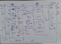
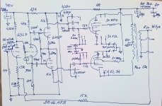
Actual schematic below:

Actual schematic below:

Last edited:
You have too many high pass C-R filters in the forward gain path. They include the 100nF-1M coupling between first two stages; the 100nF-470k coupling between 2nd and 3rd stages, the 100nF-220k coupling to output stage; and finally the output transformer itself. For unconditional LF stability you need to reduce that by at least one C-R filter, and even then need to modify the remaining CR filters to move one to well below the corner frequency of the output transformer. Williamson used a direct coupled first stage to 2nd stage, but depending on output transformer this even needed one of the corner frequencies pushed a lot lower, such as using 1-2uF coupling caps between 2nd and 3rd stages. Williamson also did a phase trick with the power supply filtering of the first two stages, which you haven't followed given the 47uF and 470uF filtering, but the coupling cap issue is likely your nemesis.
Thank You.
Late: with 20db nfb applied, using the real 8ohm speaker as load it shows occasional lf instability: is not motorboating but extremely low freq oscillation ( maybe 1-2 cps pistonic movement ). 18db it shows no issue at all ..Still not sure if is a usable circuit please ?
Late: with 20db nfb applied, using the real 8ohm speaker as load it shows occasional lf instability: is not motorboating but extremely low freq oscillation ( maybe 1-2 cps pistonic movement ). 18db it shows no issue at all ..Still not sure if is a usable circuit please ?
Last edited:
Yes the 1-2 Hz oscillation is LF instability, and it relates to the output transformer's primary winding inductance increasing and decreasing as signal level oscillates up and down. OPT primary inductance changes a lot with signal amplitude, and a good/large OPT will likely have a resonance around 1-2Hz.
I'd recommend removing the first stage coupling cap, and increasing the 2nd stage coupling cap size. That requires some care and adjustment of biasing. If you want to change the design then you really need to become a designer and be able to work through all the detailed consequences.
Some base design details of the Williamson amp are in this link, along with links to other design articles scattered across the decades: https://dalmura.com.au/static/Williamson design info.pdf
Some base design details of the Williamson amp are in this link, along with links to other design articles scattered across the decades: https://dalmura.com.au/static/Williamson design info.pdf
Ok. It is not very hard to make the first stage dc coupled. Still with 6sl7 470k into plate with 1.5k will get 100v plate voltage around which will be convenient to bias the cathodyne supplied at 400v. I wonder what You suggest for cathodyne to driver coupling caps please ? Actually they are 100nF / 470K determined a 3.4Hz pole. What I have at hand at the moment are some 470 nF which will shift to 0.72Hz. Do you think is enough please ? Thanks.I'd recommend removing the first stage coupling cap, and increasing the 2nd stage coupling cap size. That requires some care and adjustment of biasing. If you want to change the design then you really need to become a designer and be able to work through all the detailed consequences.
Some base design details of the Williamson amp are in this link, along with links to other design articles scattered across the decades: https://dalmura.com.au/static/Williamson design info.pdf
And actually no need to modify nothing else but first stage and 2nd to 3rd coupling caps 470k plate provided exactely 2.5db more gain and 1.5k biasing to 1V into cathode to provide 100v into the plate, very convenient to couple dc the cathodyne and get rid of the first rc pole...and seems it works. 20db nfb lf. stable into 8 ohm resistive load...HF compensation will follow... Thanks.
Last edited:
Ok. It is not very hard to make the first stage dc coupled. Still with 6sl7 470k into plate with 1.5k will get 100v plate voltage around which will be convenient to bias the cathodyne supplied at 400v. I wonder what You suggest for cathodyne to driver coupling caps please ? Actually they are 100nF / 470K determined a 3.4Hz pole. What I have at hand at the moment are some 470 nF which will shift to 0.72Hz. Do you think is enough please ? Thanks.
Those will help, may even eliminate the "breathing". I use 1uF in that position and have never had a low-frequency stability issue. Again, if you haven't read the link I posted at #24, it's pretty much a textbook for stabilizing a stock Williamson circuit.
This is an outstanding article revealing what the designers had in their mind about the circuit (it is so easy to understand even for a hobbyist like me). Thanks for sharing. 🤗Those will help, may even eliminate the "breathing". I use 1uF in that position and have never had a low-frequency stability issue. Again, if you haven't read the link I posted at #24, it's pretty much a textbook for stabilizing a stock Williamson circuit.
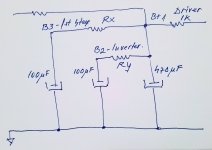
Oversized interstage caps, I found their use in my AB high power 3 stage amp which I am currently building, the results contradictory when using large output transformers with extended LF response....using fixed bias with one pole less. I have to use lower interstage cap values to avoid LF hangover and improved transient reponse; a typical circuit of their use is the step stage design and structure used in the 1st stage to diff driver in the GEC 50Watt circuit, which is also time served & well sounding although not the lowest distortion design. The transient reponse/recovery is also good ;but also note that Gillespie´s modification includes very high concertina resistances, i.e stretched time constants with the 2u2 coupling caps, and an output Zobel, not for the rising LS response but against circuit HF instability if the LS is accidentally disconnected. One doesn´t omit it with high power designs with long cables !
Bench Baron
Bench Baron
Attachments
Bench Baron, your schematic snip does not show a Williamson front end - it shows a type of paraphase splitter front end used by GEC in their 50W example - perhaps it would have been less confusing to show Fig B1 on p.121 from GEC (http://www.tubebooks.org/books/gec_approach.pdf).
If you needed to use such a LF step network in your particular amp then that clouds the issue with respect to a Williamson amp, as you have not detailed what amp you are building or its schematic or output transformer, or what CR networks and OPT corner frequency you were trying to stabilise - except that you needed to include a step network for stability. So perhaps there is no contradiction, or LF hangover and transient response issues for the OP.
If you needed to use such a LF step network in your particular amp then that clouds the issue with respect to a Williamson amp, as you have not detailed what amp you are building or its schematic or output transformer, or what CR networks and OPT corner frequency you were trying to stabilise - except that you needed to include a step network for stability. So perhaps there is no contradiction, or LF hangover and transient response issues for the OP.
Thanks for mentioning that book, Tim. I haven't looked at it in a long time and there's a lot of valuable stuff in there that is much more useful to me compared to where I was 10 years ago in my understanding. Interesting that their 30 watt Williamson only uses 14dB feedback...
Correct.....result from working late, too late with designs and physics. However, you have detailed how complex the whole subject is. I generalized a bit too much widening the complex field, although as I have shown, other designs are afflicted with the same issues.Bench Baron, your schematic snip does not show a Williamson front end - it shows a type of paraphase splitter front end used by GEC in their 50W example - perhaps it would have been less confusing to show Fig B1 on p.121 from GEC (http://www.tubebooks.org/books/gec_approach.pdf).
If you needed to use such a LF step network in your particular amp then that clouds the issue with respect to a Williamson amp, as you have not detailed what amp you are building or its schematic or output transformer, or what CR networks and OPT corner frequency you were trying to stabilise - except that you needed to include a step network for stability. So perhaps there is no contradiction, or LF hangover and transient response issues for the OP.
Thanks for including the GEC book; Appendix B p.119 contains the vitals I was trying to get hold of. In some ways it seems to contradict Gillespie´s modification of adding large amounts of interstage cap to dampen an LF pole, but we don´t know the details of the output transformer he was using.
I´ll try and get things right next time !
Bench Baron
Please someone make clear for an ignorant what's the deal with individual decoupled supply nodes for the first stage and cathodyne ? If I use one common node decoupled enough with a certain huge cap (as I did), the original arrangement with two poles still will do a difference please ? Some basic explanation apreciated.Thanks.
Ok. I get two 100uF caps and I.m ready to modify the power supply chain from using one common node for 1st stage and inverter - to individual supply nodes as original project shows. The caps are large enough to provide enough decoupling even with small series resistors used...By my point I will choose the resistors in respect with desired operating voltage, but still two questions please :1. should I follow a certain poles for this supply nodes please ? 2. May be this poles identical (say both 0.2Hz or whatever...) or should be far apart with a certain ecart please ? (say one at 0.2Hz, the other at 0.8...just for instance) . What is the whole philosophy related to choose a certain points other than operational voltage supply please ? Thank You.


In the Williamson, the gain of first stage is related to the anode load resistor value, which for mid-band is 47kohm, because the 8uF supply decoupling cap looks like a local short circuit to ground. But as the signal frequency being amplified by that stage reduces towards DC, that 8uF cap becomes a higher impedance, and at DC is an open circuit, which then means the first stage has a 47k+22k=69k anode load, and that increases the gain of the stage. However, it is the change in phase from that changing anode load that becomes important, as it improves the LF stability margin by about 20-30deg, compared to just having a whopping huge cap. One way to appreciate what is happening to the phase is to read through the articles by Roddam and Learned on step networks, as this is somewhat analogous imho, where the most phase shift is co-located at the approx 2Hz region where it provides improved phase margin as loop gain passes through 0dB. An alternative to step network theory is to use LTSpice to assess what is going on, and whether your part values are appropriate for your output transformer (which will move around in frequency with signal voltage).
- Home
- Amplifiers
- Tubes / Valves
- Williamson first stage question

