
Thanks Nelson,I would expect 10 watts into 8 ohms with 19V, 1.5A.
You will need a bigger heatsink.

Not a problem, my heatsink is 0.44 C/W

All I can say is that the output wave form will start to flatten when clipping starts. As the output voltage increases further, the waveform flattens more. So more asymmetry indicates higher level of clipping, or higher level of exceedance of maximum power. This is for single ended amplifiers, which are Class A.
By the way, using a higher impedance test load or speaker will increase the output voltage before clipping.
If Class A, but push-pull, then symmetrical clipping is possible.
By the way, using a higher impedance test load or speaker will increase the output voltage before clipping.
If Class A, but push-pull, then symmetrical clipping is possible.
The Zenductor is not a low distortion amplifier, and the difference in magnitudes of the positive and negative waveform is 2nd order harmonic distortion.
Changing the operating point of the MOSFET, so it is in a more linear region of the characteristics curve will lessen the difference in positive/negative response. A more linear region would have the curves more evenly spaced across the load line.
Changing the operating point of the MOSFET, so it is in a more linear region of the characteristics curve will lessen the difference in positive/negative response. A more linear region would have the curves more evenly spaced across the load line.
Thanks for wanting to help guys 👍
Maybe my function generator is not up to the task…the negative waveform starts to distort at -1 Vpk..while the positive stays undistorted up to + 19Vpk
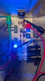
My output device is FQH44N10.
I have to buy better equipment before I continue testing.
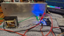
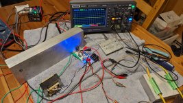
This is what I see with the equipment I currently have, maybe one of these instruments is not working ok.
Maybe my function generator is not up to the task…the negative waveform starts to distort at -1 Vpk..while the positive stays undistorted up to + 19Vpk
My output device is FQH44N10.
I have to buy better equipment before I continue testing.
This is what I see with the equipment I currently have, maybe one of these instruments is not working ok.
Something is not working properly if the output is distorting at such a low output voltage.
You can check your signal generator/oscillator by checking its output with the oscilloscope. You can then also check the signal/generator connected to your preamp (if you used a preamp in your amplifier test) with the oscilloscope. If they all check out, then the amplifier is suspect.
You can check your signal generator/oscillator by checking its output with the oscilloscope. You can then also check the signal/generator connected to your preamp (if you used a preamp in your amplifier test) with the oscilloscope. If they all check out, then the amplifier is suspect.
A bit late to the party...Hi @Vix
Have you had a chance to measure the output power into 8 ohm (just before clipping) when biased at 19Vdc, 1.5A
I tried to check it earlier but the clipping was asymmetrical (more than usual) the negative part was clipping way earlier, it got better when I increase the bias but I’d rather keep it at 1.5A
Is there anything I can do to reduce such a big asymmetry when it clips ?
Thanks
Eric
No, I did not test anything. I just enjoyed it "as it is".
With these circuits, more bias current is always welcome, as long as you don't burn anything.
If the heatsinks aren't big enough, a 12V fan, run at 6-7 V helps a lot (while remaining quiet)...
I will have everything to build a pair of these by the weekend but I didn't order IRFP048s. I do have several IRFP240s lying around which I know @Vix used. I have two 19VDC supplies I plan to use with big heatsinks so I'll bias at 1.5A. Is there much sonic difference between the two in this circuit? I don't understand MOSFET selection for audio applications very well maybe someone can point me to a resource?
I finally got a chance to build one channel (Covid last week). Thanks @e_fortier for the GBRs. Ran it on a huge heatsink at 19.5 V with the bias set to .75V across 0R56. My power supply says it's putting out 26 watts. Sounded very good but couldn't get much gain. I need to hook it up to one of my preamps when I get the other channel figured out. I have a FE 2022 and a tube preamp to try. I might cut this huge heat sink in half for two channels. I have a nice box to mount each channel in. Ran the output to a 10V sine wave (PP I think) with my function generator and didn't see clipping.
Attachments
Last edited:
- Home
- Amplifiers
- Pass Labs
- Zenductor