Go Back   Home > Forums > Blogs

Old
Rating: 2 votes, 5.00 average.

Rebuilding a Hafler DH200 Part 1

Posted 11th December 2012 at 12:42 AM by Stormrider

Doctor, Doctor

David Hafler (RIP) must have sold tons of these amps... There are always a wide selection of different models on ebay, but the DH200 and DH220 seem to be the most common. I have three of my own (2 P230's and a P125) that I cycle in and out of use. I've repaired and rebuilt several for other people, and yet I keep running into more of them. The most recent being Brokencrank's DH200, which I have documented below for reference, and to have a place to put my notes. I don't claim any of the info below to be gospel, just my experience. I also don't claim this to be a step by step guide to resuscitate your old Hafler. A basic understanding of electronics and amplifiers will be required. Know what you're doing before you do it, and you will make less mistakes. If you have questions, ask!*

Note: All of the component reference numbers (ie. R3, C14, Q10, etc...) I mention will be based on the schematics available in the manuals at Hafler.com. Because...
Stormrider's Avatar
diyAudio Member
Posted in Uncategorized
Views 12109 Comments 5 Stormrider is offline
Old
Rating: 2 votes, 5.00 average.

Featured Vacuum Tube: The 807

Posted 15th January 2013 at 11:05 PM by Miles Prower

Featured VTs: The 807

Click the image to open in full size.

807

The first of the beam formers is also one of the most enduring types: the 6L6. Developed by RCA in the mid-1930s, this type was originally intended for use as an audio final. It included other, then new, features besides the elimination of an actual, physical suppressor grid required to smooth out the screen grid "kinks". This included the now standard Octal base (up to eight pins possible, and with a keyed base for proper socket alignment) and a metal envelope. The latter was made in one of two ways: a glass envelope VT slipped into a metal shield can, or using the shield can as the envelope, with a glass base to bring out the connections. Other improvements was to give the control grid and screen grid the same pitch and wire diameter. By overlaying these two grids, the negative control grid serves to "shadow" the screen, thereby reducing the useless...
Miles Prower's Avatar
diyAudio Member
Posted in Uncategorized
Views 7751 Comments 0 Miles Prower is offline
Old
Rating: 2 votes, 5.00 average.

Featured VT: The 6BQ6

Posted 18th January 2013 at 02:45 AM by Miles Prower

The 6BQ6 as an audio final came to my attention as a chance result of finding
an old article from a Portuguese (Brazilian? -- it was written in Portuguese)
ham magazine. This described a simple AM plate modulator that claimed an output
of 30W (fixed bias) or 25W (cathode bias) that used a push-pull pair of these
VTs. You would expect to see 6L6s or 807s used in this particular application.
Why 6BQ6s, and what were they?

The 6BQ6 is a large signal beam former. It has no audio pedigree
whatsoever, and the spec sheet makes no mention of its use as an audio final.
During the 1950s, screen sizes and deflection angles increased, giving a larger
viewing area, and a shorter CRT for more compact TV sets. This development meant
that the usual audio finals and RF types became increasingly unsatisfactory for
horizontal deflection duty. New types more suited to the task were developed,
and one such type was...
Miles Prower's Avatar
diyAudio Member
Posted in Uncategorized
Views 4344 Comments 0 Miles Prower is offline
Old
Rating: 2 votes, 5.00 average.

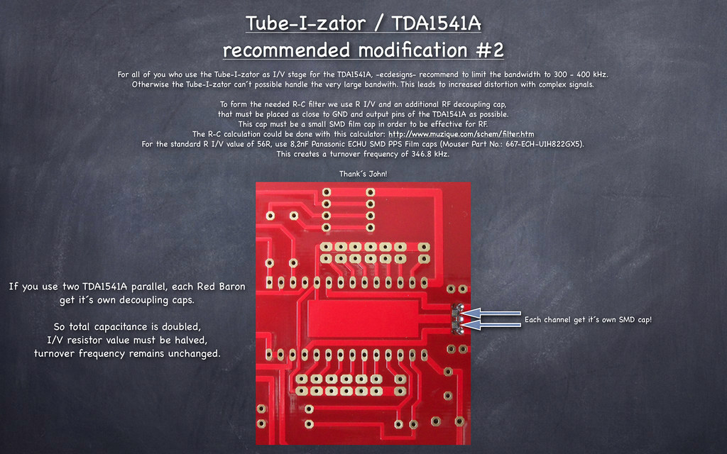
Tube-I-zator / TDA1541A recommended modification #2

Posted 24th March 2013 at 02:10 PM by dvb projekt
Updated 30th November 2016 at 09:13 AM by dvb projekt

Click the image to open in full size.
dvb projekt's Avatar
diyAudio Member
Views 1563 Comments 1 dvb projekt is offline
Old
Rating: 2 votes, 5.00 average.

Rebuilding a Hafler DH200 Part 2

Posted 16th April 2013 at 09:57 PM by Stormrider

Where was I? Right, back to the workshop and cue the music.

Sorry in advance for my photos. They get the job done, but some of them look pretty bad now. I'd retake them but the amp has long since been returned to it's owner.

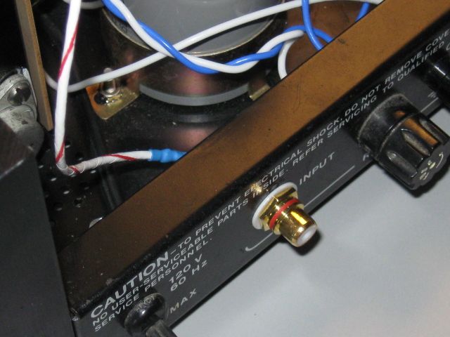
Once both channels were running happily with their new parts on the benchtop power supply I turned my limited attention to the chassis. The phenolic insulators sandwiching the RCA jacks in place were starting to crumble so, some shiny new jacks were fitted courtesy of ApexJr.com for 99 cents. The input wiring was done with 22AWG shielded wire.

Click the image to open in full size.

The pro Hafler models like the P125 and the P230 have a solid aluminum bracket for the ground connections between the main power supply caps. The DH200 and DH220 models only got some tinned wire which isn't very convenient or nice looking. I fashioned up a new bracket with some scrap...
Stormrider's Avatar
diyAudio Member
Posted in Uncategorized
Views 4436 Comments 2 Stormrider is offline
Old
Rating: 4 votes, 4.75 average.

GB F5 Guide (pcb version 2)

Posted 3rd February 2010 at 02:17 AM by cviller
Updated 14th February 2013 at 08:14 PM by cviller

As promised, I would make a guide to the boards and in particular to the additions I have made to the F5. I decided to do this in the blog, because then you can give me comments which I can use for improving the doc. However I'm not done at all, but I thought it would be nice to give you access to the BOM I have made.

IMPORTANT: Before you start stuffing your boards, you must read the manual/article written by Nelson Pass – available for download on the First Watt website (First Watt: Products: F5).

Detailed guide by Steve and Matt: https://www.diyaudio.com/forums/pass-...mentation.html

PCB
Here is a picture of the pcb.
Click image for larger version

Name:	f5_v2_front.jpg
Views:	18341
Size:	150.5 KB
ID:	99
There are no more boards available, but you can order F5 boards on the diyAudio store.


Schematics
Click image for larger version

Name:	f5_cascode_forguide.png
Views:	17168
Size:	67.7 KB
ID:	98
Optionality
With the addition of optional extra output mosfets and cascoding, there are...
Attached Thumbnails
Click image for larger version

Name:	f5_v2_front_two_output_pairs.jpg
Views:	9558
Size:	155.5 KB
ID:	102   Click image for larger version

Name:	f5_v2_front_two_output_pairs_cascode.jpg
Views:	13397
Size:	155.5 KB
ID:	103   Click image for larger version

Name:	f5_v2_front_stock_f5_rev2.jpg
Views:	7760
Size:	155.7 KB
ID:	151  
Attached Files
File Type: pdf bom.pdf (50.9 KB, 5762 views)
cviller's Avatar
diyAudio Member
Posted in Uncategorized
Views 59853 Comments 98 cviller is offline
Old
Rating: 3 votes, 4.67 average.

Tech note: Balanced lines-1

Posted 13th January 2010 at 06:54 PM by jan.didden
Updated 25th April 2016 at 07:30 AM by jan.didden

Why would one use balanced interconnects, and how can we make them work well?

Balanced lines came about at a time where very long signal lines were coming in use for telephone and later for large audio performance venues. If you use a single screened line for your signal, and the line is long, the ground current through the screen causes a voltage between the ground points of the cable ends. Since the signal send out (and received) is the difference between the voltage on the signal wire and the ground wire, the unwanted signal (noise, hum) is effectively added to the wanted (music) signal. We don’t want that.

The trick is to use TWO signal lines in parallel. You send the signal over the two lines in such a way that the signal you want to transmit is the difference between the signals on these two wires, and then at the receiving end you have an amp that reacts to the difference between the two lines, so your signal at the far end is the difference between...
Attached Thumbnails
Click image for larger version

Name:	balanced lines-1.jpg
Views:	4153
Size:	71.9 KB
ID:	90  
Attached Files
jan.didden's Avatar
diyAudio Member
Posted in Uncategorized
Views 4946 Comments 2 jan.didden is offline
Old
Rating: 3 votes, 4.67 average.

Feedback, or how to be late and be on time the same time, all the time.

Posted 3rd November 2010 at 05:19 AM by jan.didden
Updated 3rd November 2010 at 10:20 AM by jan.didden

Just a couple of days ago I posted something to try to debunk that tired old myth that 'feedback always comes too late and therefor can't work'. Apart from the fact that obviously it does work, which makes the first statement pretty stupid to begin with, here's my take on it.

The myth may result from an often repeated misconception that feedback comes 'after the fact' and therefore always comes too late.
This has been shown to not be the case over and over again but if you have no engineering background it may be difficult to grasp the concept. Let me try to help.

Obviously, there is a signal delay in an amp from input to output and back to the input through the feedback loop. Since the feedback loop is generally a pair of resistors, the bulk of the delay is in the amp. That is the case both in non-feedback as well as in feedback amps. Such delays are very small, often fractions of a microsecond, and in this context can be ignored.

What...
jan.didden's Avatar
diyAudio Member
Posted in Uncategorized
Views 3602 Comments 3 jan.didden is offline
Old
Rating: 3 votes, 4.67 average.

Using the QA400 Tips

Posted 18th December 2014 at 05:38 AM by SyncTronX
Updated 21st December 2014 at 08:52 AM by SyncTronX

For those of use that use the QA400 FFT,
here are some tips that will help us use the
product and software for measurement.

Press the Ctrl key plus an Axis, Windowing, or Measurement soft switch parameter.

For example, PRESS Ctrl + .dBV brings up a
dialog box to set External Gain & Peak Display Format:
Click the image to open in full size.

Ctrl + .dBr brings up the following:
Click the image to open in full size.


Ctrl + .X Lin:
Click the image to open in full size.


Ctrl + .X Log:
Click the image to open in full size.


The Measurements soft switch parameters as follows:

Ctrl + .Pwr:

Click the image to open in full size....
SyncTronX's Avatar
diyAudio Member
Posted in How To
Views 1592 Comments 0 SyncTronX is offline
Old
Rating: 2 votes, 4.50 average.

Cathode Follower

Posted 14th May 2010 at 11:40 PM by Miles Prower

AC Coupled CF

Click the image to open in full size.

In this schemo, Rk is the normal cathode bias resistor. Rl represents the tail load in parallel with the load impedance. Rg is the control grid DC return. The CF gives excellent high frequency performance since Miller Effect is absent, and the Cgk sees very little current since the grid and cathode are always at nearly the same potential. This makes the Cgk effectively smaller than its static value. The main component of input capacitance will be the reverse transfer capacitance: Cgp. With small signal triodes, it is easy to present a Hi-Z, Lo-C load to the driving stage. This isn't just helpful at RF.

This is another circuit which has lately come under unjustified criticism within certain audiophile circles. Much of this is unjustified on the basis that the CF is a negative feedback circuit. This view that all NFB is all bad does have a basis in fact. It has...
Miles Prower's Avatar
diyAudio Member
Posted in Uncategorized
Views 3871 Comments 0 Miles Prower is offline

New To Site? Need Help?
Copyright ©1999-2017 diyAudio