


GB F5 Guide (pcb version 2)
As promised, I would make a guide to the boards and in particular to the additions I have made to the F5. I decided to do this in the blog, because then you can give me comments which I can use for improving the doc. However I'm not done at all, but I thought it would be nice to give you access to the BOM I have made.
IMPORTANT: Before you start stuffing your boards, you must read the manual/article written by Nelson Pass available for download on the First Watt website (First Watt: Products: F5).
Detailed guide by Steve and Matt: https://www.diyaudio.com/forums/pass-...mentation.html
PCB
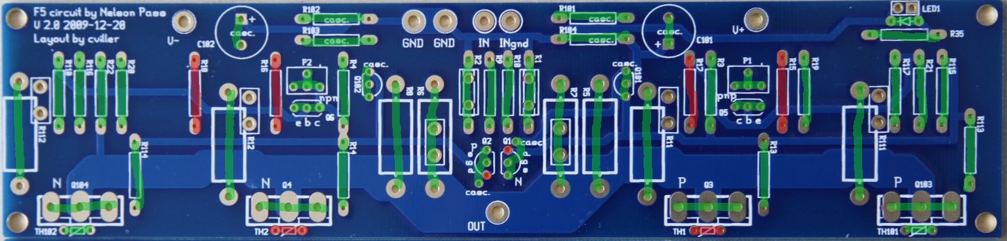
Here is a picture of the pcb.
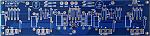
There are no more boards available, but you can order F5 boards on the diyAudio store.
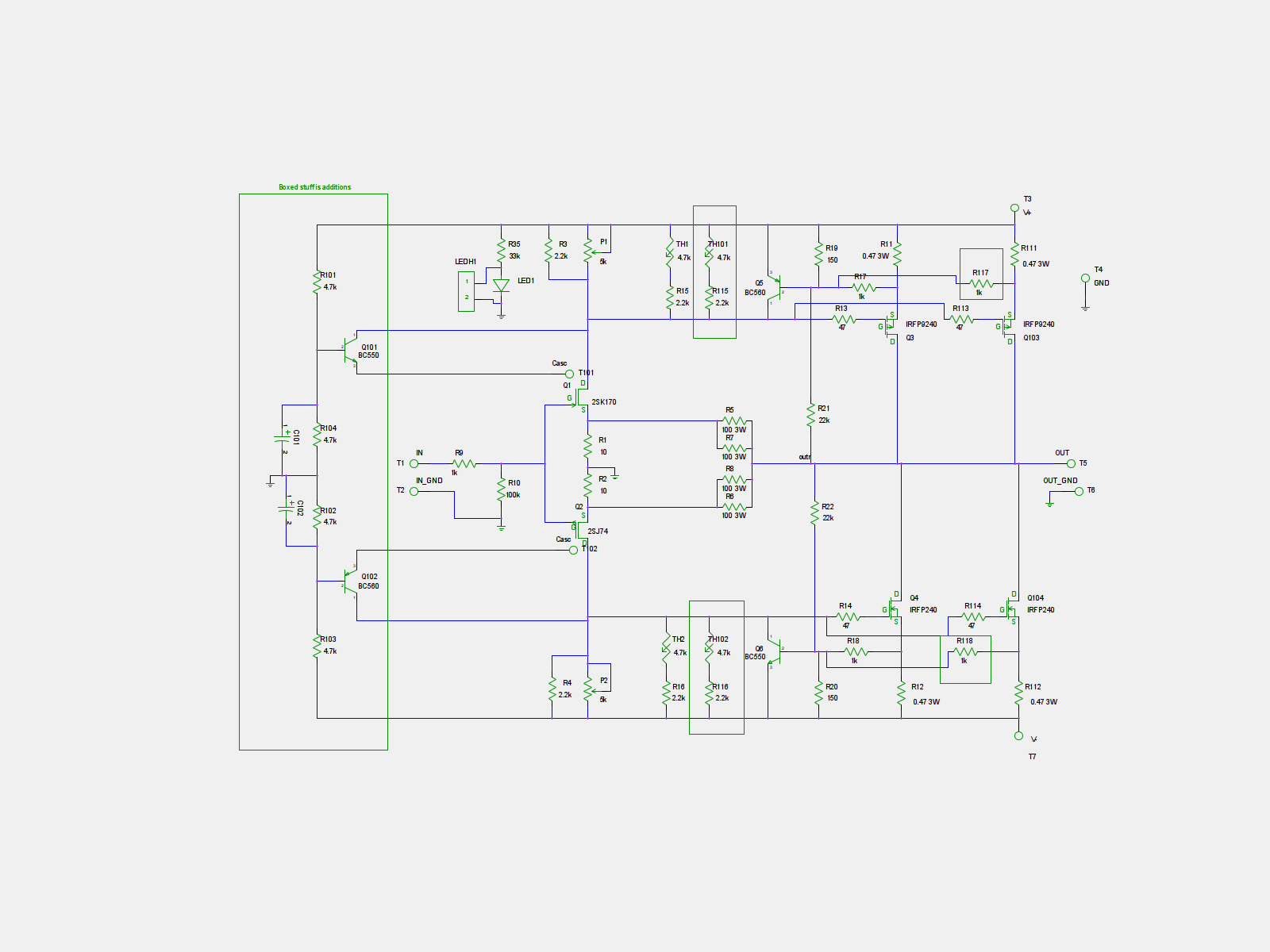
Schematics
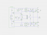
Optionality
With the addition of optional extra output mosfets and cascoding, there are many possible ways to build the amp. Here I'll try to explain some of them.
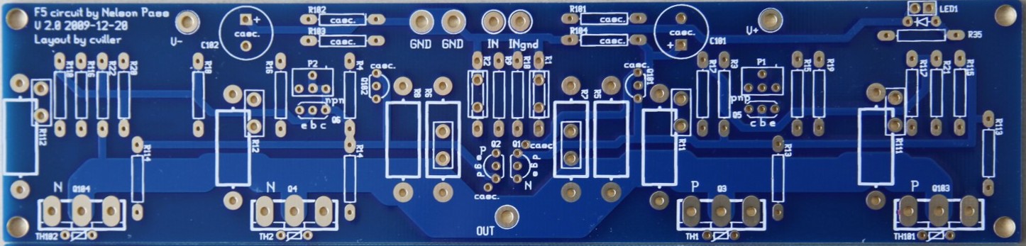
Stock F5 example
Greens are populated and reds are left open.
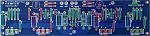
Here I have used the outputs farthest apart and notice I have also used the corresponding thermistor and sensing resistors.
Double Ouput Mosfets
Greens are populated and reds are left open.
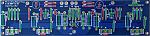
When the other output device is populated, you should not add extra thermistors, but you can chose if you want to use the inner our outer mosfet as reference - I have chosen the outer.
The output fets must be matched in pairs - the two N's should have same vgs and the P's must have same vgs.
The extra output devices will allow you to run the amp at higher currents, which is good for driving low impedance speakers. But be sure to have a large enough heatsink if you chose to crank up the bias.
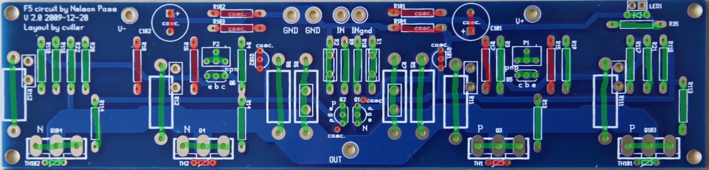
Cascode and Double Output
Greens are populated and reds are left open.
The cascoded option with double outputs requires two extra transistors and the voltage dividers. Notice that one of the legs of both jfets has to be bend slightly to connect to the hole designated "casc.".
The cascoded option is mainly there to allow for slightly higher supply voltages. Doing the cascode does require some electronics skills, because you may need to adjust some values to get the required headroom for operations. You can read more about cascodes in Nelson Pass' excellent article on the topic: https://www.passdiy.com/pdf/articles/cascode.pdf
BOM
bom.pdf
Output devices
You can use many different output devices for this amp, but the standard is Fairchilds FQA19N20C and FQA12P20C. They can be difficult to get your hands on, so you can use the IRFP parts instead.
Sourcing components
You can order component kits from various diyAudio members.
North America
jackinnj: Tech DIY Company Store (many full clone kits)
Europe
h_a: F5 amp transistor kits
FAQ
Increasing the feedback resistor will lower the amount of feedback, so you'll get more gain and distortion.
I use 14-16 gauge wire for the PSU and outputs and shielded wires for the input. I don't think this is the place where you will see the most improvement from exotic parts, but don't use crummy wire either.
You can use double outputs to lower the load on each mosfet or increase the total bias. If you increase the bias to twice the stock value, then your heatsink needs to dissipate twice as much heat.
With the stock F5, you are dissipating around 60 watt per channel, so you need a 0.3C/W sink to stay below 20C over ambient temperature.
With the double amount of dissipation, your sinks need to be 0.15C/W per channel.
IMPORTANT: Before you start stuffing your boards, you must read the manual/article written by Nelson Pass available for download on the First Watt website (First Watt: Products: F5).
Detailed guide by Steve and Matt: https://www.diyaudio.com/forums/pass-...mentation.html
PCB
Here is a picture of the pcb.
There are no more boards available, but you can order F5 boards on the diyAudio store.
Schematics
Optionality
With the addition of optional extra output mosfets and cascoding, there are many possible ways to build the amp. Here I'll try to explain some of them.
Stock F5 example
Greens are populated and reds are left open.

Here I have used the outputs farthest apart and notice I have also used the corresponding thermistor and sensing resistors.
Double Ouput Mosfets
Greens are populated and reds are left open.
When the other output device is populated, you should not add extra thermistors, but you can chose if you want to use the inner our outer mosfet as reference - I have chosen the outer.
The output fets must be matched in pairs - the two N's should have same vgs and the P's must have same vgs.
The extra output devices will allow you to run the amp at higher currents, which is good for driving low impedance speakers. But be sure to have a large enough heatsink if you chose to crank up the bias.
Cascode and Double Output
Greens are populated and reds are left open.
The cascoded option with double outputs requires two extra transistors and the voltage dividers. Notice that one of the legs of both jfets has to be bend slightly to connect to the hole designated "casc.".
The cascoded option is mainly there to allow for slightly higher supply voltages. Doing the cascode does require some electronics skills, because you may need to adjust some values to get the required headroom for operations. You can read more about cascodes in Nelson Pass' excellent article on the topic: https://www.passdiy.com/pdf/articles/cascode.pdf
BOM
bom.pdf
Output devices
You can use many different output devices for this amp, but the standard is Fairchilds FQA19N20C and FQA12P20C. They can be difficult to get your hands on, so you can use the IRFP parts instead.
Sourcing components
You can order component kits from various diyAudio members.
North America
jackinnj: Tech DIY Company Store (many full clone kits)
Europe
h_a: F5 amp transistor kits
FAQ
Quote:
What happen in F5 if I use 60 or 75 ohm in place of 50 one ?
Quote:
What cables do you use?
Quote:
Could you give more information about possible changes in bias and other settings for double mosfet option comparing to stock. What are your recommendations for the power supply/transformer and heat sinks?
With the stock F5, you are dissipating around 60 watt per channel, so you need a 0.3C/W sink to stay below 20C over ambient temperature.
With the double amount of dissipation, your sinks need to be 0.15C/W per channel.
Quote:
Thanks to AudioSan for this guidance to cascode calculation:
Rail voltage divided by (R103+R102) multiplied by R102 = coscoded voltage.
so f.ex: 35V rails / (4.75K+4.75K) x 4.75K= 17.5V to the J-fets. to get higher voltage for the J-fets, just increase R102 and/or decrease R103. and the other way around to lower the voltage.
the caps can be around 10uF. not very important
Total Comments 98
Comments
-

 Should be 2 - you only need 4 if you run multiple outputs.Posted 21st March 2012 at 11:05 AM by cviller

-
Same seems to go for other resistors (they are double counted in the BOM file)Posted 21st March 2012 at 11:52 AM by studiostevus
-
Hi Christian,
Last months I enjoyed listening the F5 build with your PASSDIY provided PCB's (v2). Hence, during my build the scheme slightly changed (p3 was added) I wonder if it is an easy step to implement p3 in your board?!?
And Can it be used as an F5T v1?
Regards,
NilsPosted 11th June 2012 at 08:07 AM by wijgers
-
I have heard about people adding P3, but I have not investigated it myself. But yes, you can configure it to a F5T - but it may require some drilling.Posted 11th June 2012 at 09:00 AM by cviller
-
 hi,
hi,
I got my last parts to day and fired up my F5c,and it didn't work I can only get .05 on the bias, and 180mv on output,I have checked the parts placement and solder ect,These boards came from the diy store and are newer than the blog,The bom is correct? for this board? schematic?
Could someone who has build this board post a picture so I can see if I have goofed up,I am cascoded and using 2 mofsets per side,Thanks!!!!!!!!!!!!!!!Posted 10th July 2012 at 01:43 AM by noSmoking
-
hi,
I changed r 101 102 103 104 to 4.7K but might have to change them again,I am all the way out on the pots and still only get .10 on the - and .039 on the + side of r11 and 12,It is playing but needs more work,rails are steady at 43 vdc +,- and about 22 at cascodes, have 3.7 across R3 and 4,,,,any help is appreciated,
I've traced out Q5,6 and they are correct,changed them from ztx to bc didn't matter,out still a 1.5 offset,somethingStupid,lol.
NSPosted 10th July 2012 at 08:10 AM by noSmoking
-
gee nothing back!
I removed the cascode,and put it to a normal F5,bias wide open,+ .04 and -at .090 reduced PS to 24vdc,
Got any suggestion!
Thanks,
NSPosted 11th July 2012 at 01:37 AM by noSmoking
-
hi,
Got It running,sounds GREAT,Thanks Cviller!Posted 11th July 2012 at 06:19 AM by noSmoking
-
Hi,
I have older (not cascoded ones) boards for F5 from diy store and parts from techdiy for F5 rev.1, which has a different schematic (i.e. for instance, R1/R2 in place of R9/R10).
Did anybody try to build F5 using such a combination?
Does the PCB require many changes?Posted 19th July 2012 at 05:31 PM by doolav
-
noSmoking,Quote:Originally Posted by noSmoking
 hi,
hi,
Got It running,sounds GREAT,Thanks Cviller!
I've been following your postings for some time and appreciate your advice and assitance.
Did you get it running with the cascode circuit operating? If so, I wondered what voltage is on your rails and whether you needed to modify any resistors to get the cascoding working well.
Thanks in advance.Posted 21st July 2012 at 09:59 PM by toxic ingestion
-
In the process of building the F5c form the diy store is there a build guide anywhere?? 32 volt rails bias?? I am cascoding with 4 op per sidePosted 31st August 2012 at 07:51 PM by mk57
-
Sorry for the lack of replies - too busy with work and our little 5 months old girl.
Regarding a guide for F5 cascode, I would recommend reading nelson pass' F5 turbo article.Posted 1st September 2012 at 06:39 AM by cviller
-
cviller. gratulation on your girl
and see. the calulator is a good thing to have here Posted 4th October 2012 at 03:52 AM by AudioSan
-
mk57. i guess you have read the calculation by nowPosted 4th October 2012 at 03:53 AM by AudioSan
-
Does anybody have these boards available? The Store has been out of stock for several months, quite annoying. Otherwise are the gerbers available or could we start a new GB?Posted 5th April 2013 at 01:05 PM by rade95
-
Hi guys - sorry for not seeing your posts. Sometimes, the notifications gets lost in my mail, but you are welcome to pm. Regarding the rectifier boards, there is a thread here with the info: https://www.diyaudio.com/forums/group...er-boards.html
Johnny, have you solved your question? Precisely, what board are you talking about? Is it the one from DIY store?
Regarding availability, I would be interested in doing another GB, but I need to check if diyaudio still wants to produce and sell the boards.Posted 5th April 2013 at 05:28 PM by cviller
-
 Sorry for another heat sink question.
But I've got some big Conrads MF35-151.5 that are 350x151.5x48 mm with a C/W for 80deg rise of .21
I realize this isn't enough for all F5c 2.2 configs, but I'd like your opinion of what setup would work for 4 Mosfets cascoded in terms of rail voltage and bias limitations to fit these in safely. Or possible suggestions of forced airflow.
Thanks
CharlesPosted 14th August 2015 at 06:24 PM by cowboy99
-
Hi Charles,
The short answer is: it depends...
I would probably not go too much up in voltage, but instead use any additional thermal headroom for increased bias. The heatsink you have is often being used for standard F5's. I have been running a stock F5 on a 400x177x50 (hifi2000) sink for years and it has never been overly hot, but I wouldn't want to crank it up too much without adding some forced air cooling.
What voltage did you have in mind? Do you have efficient speakers?Posted 17th August 2015 at 01:27 PM by cviller

