Go Back   Home > Forums > Blogs

Old

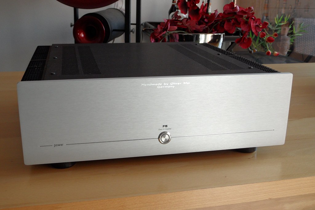
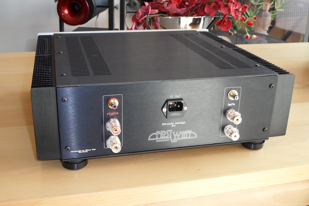
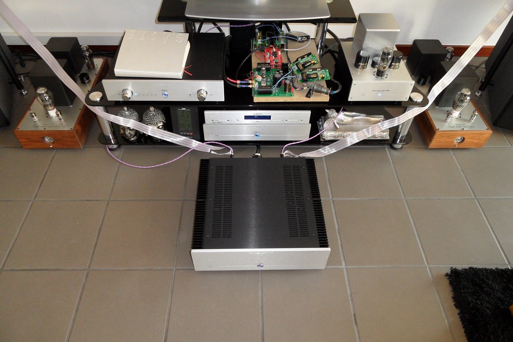
First Watt F5 Amp finished

Posted 19th February 2012 at 12:42 PM by dvb projekt
Updated 16th May 2016 at 01:58 AM by dvb projekt (Hifi-Tuning Supreme 3 fuse photo added)

My F5 is ready to burn in


Click the image to open in full size.

Click the image to open in full size.

Click the image to open in full size.

Click the image to open in full size.


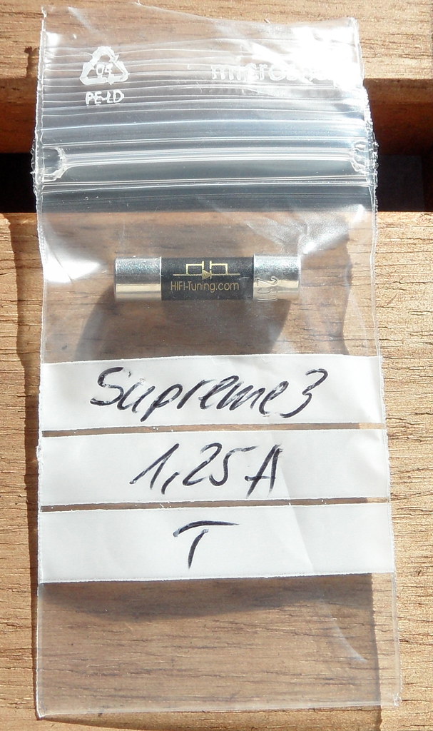
The postman delivered today the last small part for perfection...

Click the image to open in full size.

The Hifi-Tuning Supreme 3 fuse


dvb projekt's Avatar
diyAudio Member
Views 4626 Comments 11 dvb projekt is offline
Old

Voltage regulators and ... something almost as good?

Posted 17th February 2012 at 10:55 PM by rjm (RJM Audio Blog)
Updated 6th March 2012 at 05:21 PM by rjm

A real, honest-to-goodness voltage regulator has three parts: a fixed voltage reference, an error amplifier, and a pass element.

Most people only put eyeballs on the final, all-wrapped-up-in-a-tidy-IC-package version, typified by the LM7812, or with a couple of extra gain-set resistors, the LM317. These chips have a working bandwidth about about 2 kHz, as they are designed to 1) reduce 120 Hz ripple and 2) be rock stable no matter what abuse they are subjected to. As a result at audio frequencies and above they are pretty much noise generators...

Knowing this, many people have set out to build better regulators for audio work.

The most obvious route is to build a high performance LM7812 from discrete components. (Most excellent review here.) AD797 for the error amplifier, high stability, low noise voltage reference, etc. The trick though, is stability. The LM7812 is low bandwidth not because it's too cheap to manage anything better, but because...
Attached Thumbnails
Click image for larger version

Name:	x-reg mod2.png
Views:	2480
Size:	23.0 KB
ID:	600   Click image for larger version

Name:	TeddyReg-small mod rjm.png
Views:	4937
Size:	39.2 KB
ID:	601  
rjm's Avatar
rjm
diyAudio Member
Views 3532 Comments 0 rjm is offline
Old

The Not Passive Pre

Posted 16th February 2012 at 07:31 AM by hbc

Had this running for a few weeks now, and the sound coming from the Sonys altogether better, now just a bit bass heavy rather than treble shy. The speakers are mounted right next to the ceiling in the room corners, so not really a surprise.

I have simulated the crossover and equalisation circuit of the preamp section, and realised that I can add a variable resistor to adjust the amount of bass boost the circuit gives, not a horrible mod, just one pot, and a new cap, just need some time to do it.


The not passive pre has no muting circuit in at present, so power sequencing is required. I intend to make it direct coupled at the output. To do this I am planing to do a micro controller servo loop. When I made the Class A digital amplifier, mentioned earlier I used an opamp servo, and I can state that this circuit does definitely have an effect on the sound.


In the interests of minimalism the Not Passive Pre II is already being...
Attached Thumbnails
Click image for larger version

Name:	IMG_0246.JPG
Views:	381
Size:	757.3 KB
ID:	592   Click image for larger version

Name:	IMG_0247.JPG
Views:	389
Size:	800.5 KB
ID:	593   Click image for larger version

Name:	IMG_0249.jpg
Views:	887
Size:	404.9 KB
ID:	594  
hbc
diyAudio Member
Posted in Uncategorized
Views 1542 Comments 0 hbc is offline
Old

"Activator 2" FET preamp for .. guitars and basses?

Posted 13th February 2012 at 11:48 PM by rjm (RJM Audio Blog)
Updated 2nd April 2012 at 02:04 AM by rjm

I have been doing a web-dredge, searching for simple, single supply, transistor buffer/gain stages, preferably FET-based.

This one seems interesting.

The designer, Henry Nurdin, has kindly posted a full schematic.

Ignore the fact for a moment that it's designed as a tiny battery-operated module to retrofit into electric guitars, the basic circuit block with 5-6 dB non-inverting gain could be used as a front end for a headphone buffer stage like, I'm thinking especially, the Szekeres MOSFET buffer.

That's if the bandwidth is sufficient for high-end audio (should be!?) and, slightly more worrisome, acceptable gain matching between channels can be achieved without resorting to trim pots.

This circuit reminds me of something. ... Sziklai pair? Time to do some more dredging...

Ah, bingo!

Update:

And with some jiggery-pockery this is taking shape as a (yet another) headphone amplifier....
Attached Thumbnails
Click image for larger version

Name:	Activator 2.png
Views:	14005
Size:	25.4 KB
ID:	588   Click image for larger version

Name:	activator_naked.jpg
Views:	598
Size:	5.2 KB
ID:	589   Click image for larger version

Name:	activator_module.jpg
Views:	416
Size:	3.4 KB
ID:	590   Click image for larger version

Name:	aplocalypse.png
Views:	15060
Size:	18.8 KB
ID:	591   Click image for larger version

Name:	Jmo2 11a.png
Views:	1685
Size:	50.5 KB
ID:	595  

Click image for larger version

Name:	DSC_3618 1280.jpg
Views:	1193
Size:	380.5 KB
ID:	634  
rjm's Avatar
rjm
diyAudio Member
Views 7783 Comments 0 rjm is offline
Old
Rating: 2 votes, 5.00 average.

Converting Eagle printed circuit board layout files to Gerber format

Posted 11th February 2012 at 12:20 AM by rjm (RJM Audio Blog)
Updated 29th January 2017 at 03:13 AM by rjm

File this under "things-I-should-have-learnt-to-do-many-years-ago-but-was-too-lazy-to-bother".

Many pcb fab outfits that do business with hobbyists and DIYers choose to accept Eagle .brd files, which means they do the conversion to Gerber output so you don't have to. I've relied on that for far too long, but when an error showed up in one the .pdf proofs on the last batch of boards I sent out for fabrication, they asked me to send the Gerber files instead. So I bit the bullet and after a couple of false starts managed to give them what they wanted. Looking back at it, it was easy and something I should have learnt, as I wrote up above, years ago, but, for posterity, here's how it's done:

Eagle 6 on Windows
  1. Make a working folder for the Gerber files.
  2. Copy the Eagle board (.brd) file to this directory.
  3. Open Eagle (version 6.1)
  4. Select menu item "file/open/CAM job"
  5. The open file dialog appears, defaulting to the Eagle CAM
...
rjm's Avatar
rjm
diyAudio Member
Views 8490 Comments 3 rjm is offline
Old

Audio op amp comparison NE5534A vs. OPA134

Posted 10th February 2012 at 11:49 PM by rjm (RJM Audio Blog)
Updated 11th February 2012 at 03:48 AM by rjm

Finally got around to some more comparison listening with the Sapphire headphone amplifier. To recap: the circuit has an open loop diamond buffer output, so the op amp is just providing voltage gain. It configured for a non-inverting gain of 21 dB to match my 300 ohm HD600 headphones. Pretty much textbook operating conditions.

The op amp inputs are impedance balanced at about 1 kohm. This is about the crossover point where you start thinking about using FET input stages, but BJTs should still be fine.

I'm interested to see if there is a definite signature to a FET-input opamp. The original build called for an OPA134, which is a JFET input circuit. I tried the OPA27, which is a low-noise, high-input-current BJT design, and last night I tried the NE5534A, a classic general purpose audio opamp with bipolar inputs.

I've long been in agreement with Douglas Self on the NE5532/NE5534 : anyone who reports these op amps sound bad is either not using...
rjm's Avatar
rjm
diyAudio Member
Posted in The Lab
Views 9973 Comments 1 rjm is offline
Old

RJM Z-reg + Pass B1

Posted 4th February 2012 at 12:53 AM by rjm (RJM Audio Blog)
Updated 4th February 2012 at 01:01 AM by rjm

I was asked to suggest a voltage regulator for the First Watt (Pass DIY) B1 buffer. One thing led to another and the next thing I'd sketched up a circuit board for the buffer as well as the regulator.

It's like a B-board, but with the JFET buffer instead of the diamond buffer, and with a single supply and, hence, the coupling caps front and back. Since it's using JFETs for the buffer I used a JFET for the pass device in the regulator, too.

Full credit to Nelson Pass for his design.

Eagle files do not show 2SK170 because the package is not in Eagle. All transistors 2SK170 or equivalent. Zener is 18-22V DO35 or DO41 i.e. Vishay BZX85. V++ is 5-15 V above whatever you select the Zener reference to be.
Attached Thumbnails
Click image for larger version

Name:	b1-10c-brd.png
Views:	4717
Size:	19.7 KB
ID:	586   Click image for larger version

Name:	b1-10c-sch.png
Views:	5963
Size:	21.0 KB
ID:	587  
Attached Files
File Type: zip Pass B1 RJM 10c.zip (61.8 KB, 545 views)
rjm's Avatar
rjm
diyAudio Member
Views 4730 Comments 4 rjm is offline
Old

The Z-reg

Posted 1st February 2012 at 11:58 PM by rjm (RJM Audio Blog)
Updated 2nd April 2012 at 02:02 AM by rjm

This is a followup of sorts to the X-reg, though there is nothing original about the circuit this time around.

It's just a Zener voltage regulator with a series pass transistor. I lifted this particular configuration from the Pionner C-21 preamplifier and re-tuned it for op amp applications. My main interest here is trying to make a small and convenient board layout.

I've used this circuit block already in the Sapphire amp and come away impressed.

The output is about 1 V less than the Zener voltage, and the input voltage should be about 3-6 V above the Zener reference voltage. I'm working here with 17 V unregulated supply and 12 V Zeners, but the values can be reconfigured easily enough for any output from 4-24 V

This is a low current circuit. If you are just powering a few op amps, no heatsinks are needed. Above 25 mA small heatsinks are a good idea. The circuit is not designed for output currents above 100 mA.
Attached Thumbnails
Click image for larger version

Name:	zreg10d-brd.png
Views:	1880
Size:	17.4 KB
ID:	583   Click image for larger version

Name:	zreg10d-sch.png
Views:	1481
Size:	20.2 KB
ID:	584  
Attached Files
rjm's Avatar
rjm
diyAudio Member
Views 1167 Comments 0 rjm is offline
Old

Current Feedback Amplifier

Posted 31st January 2012 at 06:15 AM by rjm (RJM Audio Blog)
Updated 31st January 2012 at 06:22 AM by rjm

Found this today: DC Coupled Amplifiers for Audio from an 11 year old web page by one Knut Harald Nygaard.

I've taken some minor liberties with the circuit, shown in the second, color image below. Replaced the current sources with resistors and moved the output buffer out of the feedback loop.

Note the resultant double symmetry of the dual-diamond buffer topology, highlighted in blue.
Attached Thumbnails
Click image for larger version

Name:	dcff15 original.png
Views:	4755
Size:	7.6 KB
ID:	581   Click image for larger version

Name:	dcff15 rm mod color.png
Views:	4819
Size:	14.6 KB
ID:	582  
Attached Files
rjm's Avatar
rjm
diyAudio Member
Posted in The Lab
Views 4077 Comments 2 rjm is offline
Old

Protoamp project.

Posted 29th January 2012 at 08:52 PM by DigitalJunkie

So,I've been pondering this for a while,and I'm going to finally build it.

Basic idea- Fairly simple Push-Pull amplifier,that will deliver ~50Wpc,Using common/available tubes.
I decided to go with the 'usual' octals,since they are all a similar basing/pinout(7ac?).
This leaves us open to use 6L6,EL34,6550,KTxx,etc. for output tubes.
We'll have to have a -Vg1 supply with a wide voltage range to cover the needs of all those tubes,shouldn't be a problem.

The power transformer is a big 1kva/500W beast,used in the Tektronix 545A. (P/N 120-120)
Pete Millett was kind enough to post some data on this transformer,and a few others here:
Tek power transformers

The output transformers are rated ~100W,they came from a pair of old RCA MI-12188A amps.
They are ~3.5-4.0K (p-p) primary impedance.
There is some information on these amplifiers/transformers here:
The Shrine of the Ancient and Most Excellent RCA MI-12188A Power Amplifier...
diyAudio Member
Posted in Uncategorized
Views 1583 Comments 5 DigitalJunkie is offline

New To Site? Need Help?
Copyright ©1999-2017 diyAudio